粒子系统:颜色和深度纹理
深入探索Unity粒子系统的渲染技术,包括翻书动画、近距离淡入淡出、软粒子和扭曲效果的实现原理与实践。
- 支持翻页书、近景淡入淡出、柔和以及扭曲粒子效果。
- 确定片段深度,用于正交和透视投影。
- 复制并采样颜色和深度缓冲区。
无光照粒子
粒子系统可以使用任何材质,所以我们的渲染管线已经可以渲染它们,但有一些限制。在本教程中,我们只考虑无光照粒子。有光照的粒子工作方式相同,只是有更多的着色器属性和光照计算。
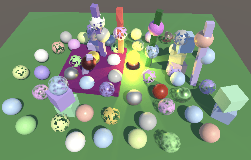
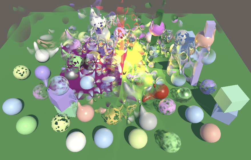
我为粒子设置了一个新场景,它是已有测试场景的变体。场景中有几个长垂直立方体和一个明亮的黄色灯泡,作为粒子系统的背景。
粒子系统
通过 GameObject / Effects / Particle System 创建一个粒子系统,并将其放置在地面平面下方一点。我假设你已经知道如何配置粒子系统,不会详细讨论这些内容。如果不熟悉,请查看 Unity 的文档来学习特定模块及其设置。
默认系统使粒子向上移动并填充一个锥形区域。如果我们为它分配无光照材质,粒子将显示为与相机平面对齐的纯白色方块。它们会突然出现和消失,但因为它们从平面下方开始,所以看起来像是从地面升起。
无光照粒子着色器
我们可以使用无光照着色器来渲染粒子,但让我们为它们创建一个专用的着色器。它从无光照着色器的副本开始,将菜单项更改为 Custom RP/Particles/Unlit。此外,由于粒子总是动态的,所以不需要 meta pass。
1
2
3
4
5
6
7
8
9
10
11
12
13
Shader "Custom RP/Particles/Unlit" {
    ....
    SubShader {
        ....
        //Pass {
        //    Tags {
        //        "LightMode" = "Meta"
        //    }
        //    ....
        //}
    }
    CustomEditor "CustomShaderGUI"
}
使用这个着色器创建一个专用的无光照粒子材质,然后让粒子系统使用它。目前它等同于之前的无光照材质。粒子系统也可以设置为渲染网格,如果材质和粒子系统都启用了阴影,甚至可以渲染阴影。然而,GPU 实例化不起作用,因为粒子系统为此使用程序化绘制,这在本教程中不会涉及。相反,所有粒子网格都会被合并成一个单一的网格,就像广告牌粒子一样。
从现在开始,我们将只关注没有阴影的广告牌粒子。这是一个单个粒子的基础贴图,包含一个简单的平滑淡出的白色圆盘。

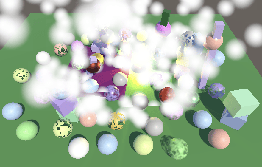
当使用这个纹理来渲染淡出粒子时,我们得到一个简单的效果,看起来像是白色烟雾从地面冒出。为了使其更令人信服,将发射速率增加到 100 左右。
顶点颜色
可以为每个粒子使用不同的颜色。演示这一点的最简单方法是将起始颜色设置为随机选择黑色和白色。然而,这样做目前不会改变粒子的外观。为了使其工作,我们必须在着色器中添加对顶点颜色的支持。我们不会为粒子创建新的 HLSL 文件,而是将支持添加到 UnlitPass 中。
第一步是添加一个带有 COLOR 语义的 float4 顶点属性。
1
2
3
4
5
6
struct Attributes {
    float3 positionOS : POSITION;
    float4 color : COLOR;
    float2 baseUV : TEXCOORD0;
    UNITY_VERTEX_INPUT_INSTANCE_ID
};
也将其添加到 Varyings 中,并在 UnlitPassVertex 中传递它,但仅在定义了 _VERTEX_COLORS 时。这样我们可以根据需要启用和禁用顶点颜色支持。
1
2
3
4
5
6
7
8
9
10
11
12
13
14
15
16
17
struct Varyings {
    float4 positionCS : SV_POSITION;
    #if defined(_VERTEX_COLORS)
        float4 color : VAR_COLOR;
    #endif
    float2 baseUV : VAR_BASE_UV;
    UNITY_VERTEX_INPUT_INSTANCE_ID
};

Varyings UnlitPassVertex (Attributes input) {
    ....
    #if defined(_VERTEX_COLORS)
        output.color = input.color;
    #endif
    output.baseUV = TransformBaseUV(input.baseUV);
    return output;
}
接下来,在 UnlitInput 中为 InputConfig 添加一个颜色字段,默认设置为不透明白色,并将其纳入 GetBase 的结果中。
1
2
3
4
5
6
7
8
9
10
11
12
13
14
15
16
17
struct InputConfig {
    float4 color;
    float2 baseUV;
};

InputConfig GetInputConfig (float2 baseUV) {
    InputConfig c;
    c.color = 1.0;
    c.baseUV = baseUV;
    return c;
}
....
float4 GetBase (InputConfig c) {
    float4 baseMap = SAMPLE_TEXTURE2D(_BaseMap, sampler_BaseMap, c.baseUV);
    float4 baseColor = INPUT_PROP(_BaseColor);
    return baseMap * baseColor * c.color;
}
回到 UnlitPass,如果插值的顶点颜色存在,则在 UnlitPassFragment 中将其复制到配置中。
1
2
3
4
InputConfig config = GetInputConfig(input.baseUV);
#if defined(_VERTEX_COLORS)
    config.color = input.color;
#endif
最后,为了将顶点颜色支持添加到 UnlitParticles,需要向其添加一个切换着色器属性。
1
2
[HDR] _BaseColor("Color", Color) = (1.0, 1.0, 1.0, 1.0)
[Toggle(_VERTEX_COLORS)] _VertexColors ("Vertex Colors", Float) = 0
以及相应的定义关键字的着色器特性。如果你也希望常规的 Unlit 着色器支持顶点颜色,也可以这样做。
1
#pragma shader_feature _VERTEX_COLORS
现在我们获得了彩色粒子。此时粒子排序成为一个问题。如果所有粒子颜色相同,它们的绘制顺序无关紧要,但如果它们不同,我们需要按距离排序以获得正确的结果。请注意,当基于距离排序时,由于视角位置的变化,粒子可能会突然交换绘制顺序,就像任何透明对象一样。
翻书动画
广告牌粒子可以通过循环播放不同的基础贴图来实现动画效果。Unity 将这些称为翻书粒子。这是通过使用规则网格布局的纹理图集来完成的,比如这个包含 4×4 网格的循环噪声图案的纹理。

创建一个使用翻书贴图的新无光照粒子材质,然后复制我们的粒子系统并让它使用该翻书材质。停用单粒子版本,这样我们只看到翻书系统。由于每个粒子现在代表一小片云,将它们的大小增加到 2 左右。启用粒子系统的 Texture Sheet Animation 模块,将其配置为 4×4 翻书,使其从随机帧开始,并在粒子的生命周期内循环播放一次。
可以通过在 50% 的时间内沿 X 和 Y 随机翻转粒子、从任意旋转开始以及使粒子以随机速度旋转来增加额外的变化。
翻书混合
当系统运动时,很明显粒子循环播放了几帧,因为翻书帧率非常低。对于生命周期为 5 秒的粒子,帧率是 3.2 帧每秒。这可以通过在连续帧之间进行混合来平滑过渡。这需要我们向着色器发送第二对 UV 坐标和一个动画混合因子。
我们通过在 Renderer 模块中启用自定义顶点流来实现。添加 UV2 和 AnimBlend。你也可以移除 normal 流,因为我们不需要它。
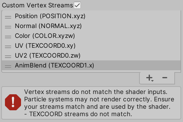
添加流后,会显示一个错误,指示粒子系统与当前使用的着色器之间不匹配。在我们在着色器中消耗这些流之后,此错误将消失。向 UnlitParticle 添加一个着色器关键字切换属性,以控制是否支持翻书混合。
1
2
[Toggle(_VERTEX_COLORS)] _VertexColors ("Vertex Colors", Float) = 0
[Toggle(_FLIPBOOK_BLENDING)] _FlipbookBlending ("Flipbook Blending", Float) = 0
以及相应的着色器特性。
1
#pragma shader_feature _FLIPBOOK_BLENDING
如果启用了翻书混合,则两对 UV 都通过 TEXCOORD0 提供,因此它必须是 float4 而不是 float2。混合因子作为单个 float 通过 TEXCOORD1 提供。
1
2
3
4
5
6
7
8
9
10
11
struct Attributes {
    float3 positionOS : POSITION;
    float4 color : COLOR;
    #if defined(_FLIPBOOK_BLENDING)
        float4 baseUV : TEXCOORD0;
        float flipbookBlend : TEXCOORD1;
    #else
        float2 baseUV : TEXCOORD0;
    #endif
    UNITY_VERTEX_INPUT_INSTANCE_ID
};
如果需要,我们将新数据作为单个 float3 flipbookUVB 字段添加到 Varyings 中。
1
2
3
4
5
6
7
8
struct Varyings {
    ....
    float2 baseUV : VAR_BASE_UV;
    #if defined(_FLIPBOOK_BLENDING)
        float3 flipbookUVB : VAR_FLIPBOOK;
    #endif
    UNITY_VERTEX_INPUT_INSTANCE_ID
};
调整 UnlitPassVertex,使其在适当时将所有相关数据复制到其中。
1
2
3
4
5
6
7
8
9
Varyings UnlitPassVertex (Attributes input) {
    ....
    output.baseUV.xy = TransformBaseUV(input.baseUV.xy);
    #if defined(_FLIPBOOK_BLENDING)
        output.flipbookUVB.xy = TransformBaseUV(input.baseUV.zw);
        output.flipbookUVB.z = input.flipbookBlend;
    #endif
    return output;
}
也将 flipbookUVB 添加到 InputConfig,以及一个布尔值来指示是否启用了翻书混合(默认情况下不启用)。
1
2
3
4
5
6
7
8
9
10
11
12
13
struct InputConfig {
    float4 color;
    float2 baseUV;
    float3 flipbookUVB;
    bool flipbookBlending;
};

InputConfig GetInputConfig (float2 baseUV) {
    ....
    c.flipbookUVB = 0.0;
    c.flipbookBlending = false;
    return c;
}
如果启用了翻书混合,我们必须在 GetBase 中第二次采样基础贴图,使用翻书 UV,然后根据混合因子从第一个样本插值到第二个样本。
1
2
3
4
5
6
7
8
9
10
11
float4 GetBase (InputConfig c) {
    float4 baseMap = SAMPLE_TEXTURE2D(_BaseMap, sampler_BaseMap, c.baseUV);
    if (c.flipbookBlending) {
        baseMap = lerp(
            baseMap, SAMPLE_TEXTURE2D(_BaseMap, sampler_BaseMap, c.flipbookUVB.xy),
            c.flipbookUVB.z
        );
    }
    float4 baseColor = INPUT_PROP(_BaseColor);
    return baseMap * baseColor * c.color;
}
最后,在 UnlitPassFragment 中适当地覆盖默认配置以激活翻书混合。
1
2
3
4
5
6
7
#if defined(_VERTEX_COLORS)
    config.color = input.color;
#endif
#if defined(_FLIPBOOK_BLENDING)
    config.flipbookUVB = input.flipbookUVB;
    config.flipbookBlending = true;
#endif
相机近处淡出
当相机处于粒子系统内部时,粒子最终会非常接近相机的近平面,也会从一侧穿过到另一侧。粒子系统有一个 Renderer / Max Particle Size 属性,可以防止单个广告牌粒子覆盖窗口的太多区域。一旦它们达到最大可见大小,它们看起来会滑出视野,而不是随着接近近平面而变得更大。
处理接近近平面的粒子的另一种方法是根据它们的片段深度淡出它们。当穿过代表大气效果的粒子系统时,这看起来会更好。
片段数据
我们已经在片段函数中拥有了片段深度。它通过带有 SV_POSITION 语义的 float4 提供。我们已经使用了它的 XY 分量进行抖动,但现在让我们正式声明我们正在使用片段数据。
在顶点函数中,SV_POSITION 表示顶点的裁剪空间位置,作为 4D 齐次坐标。但在片段函数中,SV_POSITION 表示片段的屏幕空间(也称为窗口空间)位置。空间转换由 GPU 执行。为了明确这一点,让我们在所有 Varyings 结构体中将 positionCS 重命名为 positionCS_SS。
1
float4 positionCS_SS : SV_POSITION;
在相应的顶点函数中也进行调整。
1
output.positionCS_SS = TransformWorldToHClip(positionWS);
接下来,我们将引入一个新的 Fragment HLSL 包含文件,其中包含一个 Fragment 结构体和一个 GetFragment 函数,该函数在给定 float4 屏幕空间位置向量的情况下返回片段。最初,片段只有一个 2D 位置,它来自屏幕空间位置的 XY 分量。这些是带有 0.5 偏移的纹素坐标。屏幕左下角纹素的坐标是 (0.5, 0.5),它右边的纹素是 (1.5, 0.5),依此类推。
1
2
3
4
5
6
7
8
9
10
11
12
13
14
#ifndef FRAGMENT_INCLUDED
#define FRAGMENT_INCLUDED

struct Fragment {
    float2 positionSS;
};

Fragment GetFragment (float4 positionSS) {
    Fragment f;
    f.positionSS = positionSS.xy;
    return f;
}

#endif
在所有其他包含语句之后,在 Common 中包含此文件,然后调整 ClipLOD,使其第一个参数是 Fragment 而不是 float4。
1
2
3
4
5
6
7
8
9
10
11
#include "Packages/com.unity.render-pipelines.core/ShaderLibrary/UnityInstancing.hlsl"
#include "Packages/com.unity.render-pipelines.core/ShaderLibrary/SpaceTransforms.hlsl"
#include "Packages/com.unity.render-pipelines.core/ShaderLibrary/Packing.hlsl"
#include "Fragment.hlsl"
....
void ClipLOD (Fragment fragment, float fade) {
    #if defined(LOD_FADE_CROSSFADE)
        float dither = InterleavedGradientNoise(fragment.positionSS, 0);
        clip(fade + (fade < 0.0 ? dither : -dither));
    #endif
}
此时,让我们也在 Common 中定义通用的线性和点钳位采样器状态,因为我们稍后会在多个地方使用它们。在包含 Fragment 之前这样做。
1
2
3
4
5
6
#include "Packages/com.unity.render-pipelines.core/ShaderLibrary/Packing.hlsl"

SAMPLER(sampler_linear_clamp);
SAMPLER(sampler_point_clamp);

#include "Fragment.hlsl"
然后从 PostFXStackPasses 中删除通用采样器定义,因为这现在是一个会导致编译器错误的重复定义。
1
2
TEXTURE2D(_PostFXSource2);
//SAMPLER(sampler_linear_clamp);
接下来,将片段添加到 LitInput 和 UnlitInput 的 InputConfig 结构体中。然后将屏幕空间位置向量作为第一个参数添加到 GetInputConfig 函数中,这样它们可以用它调用 GetFragment。
1
2
3
4
5
6
7
8
9
10
struct InputConfig {
    Fragment fragment;
    ....
};

InputConfig GetInputConfig (float4 positionSS, ....) {
    InputConfig c;
    c.fragment = GetFragment(positionSS);
    ....
}
在所有调用 GetInputConfig 的地方添加参数。
1
InputConfig config = GetInputConfig(input.positionCS_SS, ....);
然后调整 LitPassFragment,使其在获取配置后调用 ClipLOD,以便可以将片段传递给它。还将片段的位置传递给 InterleavedGradientNoise,而不是直接使用 input.positionCS_SS。
1
2
3
4
5
6
7
8
9
10
float4 LitPassFragment (Varyings input) : SV_TARGET {
    UNITY_SETUP_INSTANCE_ID(input);
    //ClipLOD(input.positionSS.xy, unity_LODFade.x);

    InputConfig config = GetInputConfig(input.positionCS_SS, input.baseUV);
    ClipLOD(config.fragment, unity_LODFade.x);
    ....
    surface.dither = InterleavedGradientNoise(config.fragment.positionSS, 0);
    ....
}
ShadowCasterPassFragment 也必须更改,以便在获取配置后进行裁剪。
1
2
3
4
5
6
7
8
9
10
11
12
13
14
15
void ShadowCasterPassFragment (Varyings input) {
    UNITY_SETUP_INSTANCE_ID(input);
    //ClipLOD(input.positionCS.xy, unity_LODFade.x);

    InputConfig config = GetInputConfig(input.positionCS_SS, input.baseUV);
    ClipLOD(config.fragment, unity_LODFade.x);

    float4 base = GetBase(config);
    #if defined(_SHADOWS_CLIP)
        clip(base.a - GetCutoff(config));
    #elif defined(_SHADOWS_DITHER)
        float dither = InterleavedGradientNoise(input.positionSS.xy, 0);
        clip(base.a - dither);
    #endif
}
片段深度
要在相机附近淡出粒子,我们需要知道片段的深度。所以向 Fragment 添加一个深度字段。
1
2
3
4
struct Fragment {
    float2 positionSS;
    float depth;
};
片段深度存储在屏幕空间位置向量的最后一个分量中。这是用于执行透视除法以将 3D 位置投影到屏幕上的值。这是视图空间深度,因此它是距相机 XY 平面的距离,而不是其近平面的距离。
1
2
3
4
5
6
Fragment GetFragment (float4 positionCS_SS) {
    Fragment f;
    f.positionSS = positionSS.xy;
    f.depth = positionSS.w;
    return f;
}
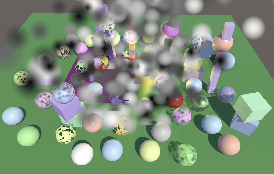
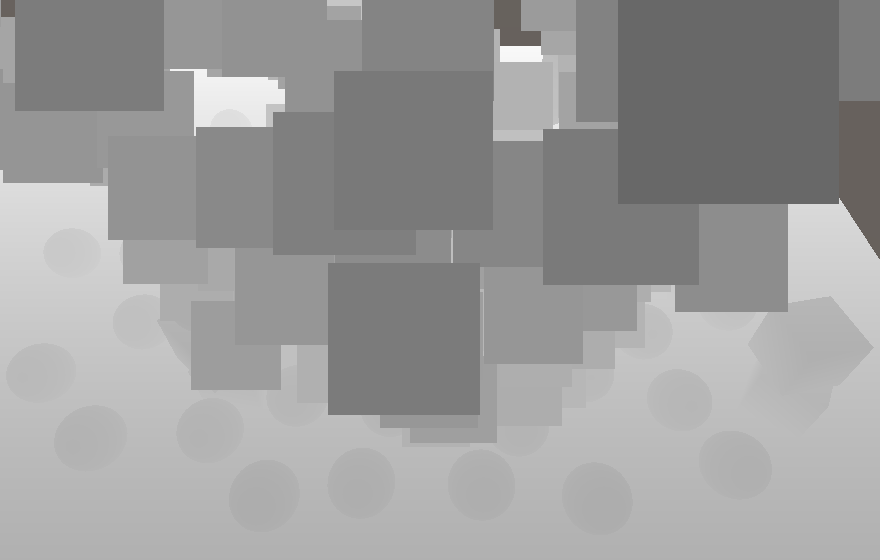
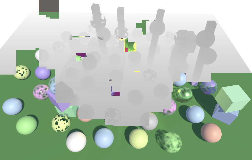
我们可以通过在 LitPassFragment 和 UnlitPassFragment 中直接返回片段深度来验证这是正确的,将其缩小以便我们可以看到它作为灰度渐变。
1
2
InputConfig config = GetInputConfig(input.positionCS_SS, input.baseUV);
return float4(config.fragment.depth.xxx / 20.0, 1.0);
正交深度
上述方法仅在使用透视相机时有效。当使用正交相机时,不存在透视除法,因此屏幕空间位置向量的最后一个分量始终为 1。
我们可以通过向 UnityInput 添加一个 float4 unity_OrthoParams 字段来确定我们是否在处理正交相机,Unity 通过该字段将有关正交相机的信息传达给 GPU。
1
2
float4 unity_OrthoParams;
float4 _ProjectionParams;
对于正交相机,其最后一个分量将为 1,否则将为 0。在 Common 中添加一个 IsOrthographicCamera 函数来使用这一事实,在包含 Fragment 之前定义它,以便我们可以在那里使用它。如果你永远不会使用正交相机,可以硬编码它返回 false,或者通过着色器关键字来控制。
1
2
3
4
5
bool IsOrthographicCamera () {
    return unity_OrthoParams.w;
}

#include "Fragment.hlsl"
对于正交相机,我们能做的最好的事情是依赖屏幕空间位置向量的 Z 分量,它包含片段的转换后的裁剪空间深度。这是用于深度比较的原始值,如果启用深度写入,则会写入深度缓冲区。它是 0-1 范围内的值,对于正交投影是线性的。要将其转换为视图空间深度,我们必须将其按相机的近远范围缩放,然后添加近平面距离。近距离和远距离存储在 _ProjectionParams 的 Y 和 Z 分量中。如果使用反转深度缓冲区,我们还需要反转原始深度。在一个新的 OrthographicDepthBufferToLinear 函数中执行此操作,也在包含 Fragment 之前在 Common 中定义。
1
2
3
4
5
6
7
8
float OrthographicDepthBufferToLinear (float rawDepth) {
    #if UNITY_REVERSED_Z
        rawDepth = 1.0 - rawDepth;
    #endif
    return (_ProjectionParams.z - _ProjectionParams.y) * rawDepth + _ProjectionParams.y;
}

#include "Fragment.hlsl"
现在 GetFragment 可以检查是否使用正交相机,如果是,则依赖 OrthographicDepthBufferToLinear 来确定片段深度。
1
2
f.depth = IsOrthographicCamera() ?
    OrthographicDepthBufferToLinear(positionSS.z) : positionSS.w;
在验证两种相机类型的片段深度都正确后,从 LitPassFragment 和 UnlitPassFragment 中删除调试可视化。
1
//return float4(config.fragment.depth.xxx / 20.0, 1.0);
基于距离的淡出
回到 UnlitParticles 着色器,添加一个 Near Fade 关键字切换属性,以及使其距离和范围可配置的属性。距离决定粒子应该完全消失时距离相机平面的距离。这是相机平面,而不是其近平面。因此应该使用至少近平面的值。1 是一个合理的默认值。范围控制过渡区域的长度,在该区域内粒子将线性淡出。同样,1 是一个合理的默认值,并且至少必须是一个小的正值。
1
2
3
[Toggle(_NEAR_FADE)] _NearFade ("Near Fade", Float) = 0
_NearFadeDistance ("Near Fade Distance", Range(0.0, 10.0)) = 1
_NearFadeRange ("Near Fade Range", Range(0.01, 10.0)) = 1
添加一个着色器特性来启用近距离淡出。
1
#pragma shader_feature _NEAR_FADE
然后在 UnlitInput 的 UnityPerMaterial 缓冲区中包含距离和范围。
1
2
3
4
5
6
7
8
UNITY_INSTANCING_BUFFER_START(UnityPerMaterial)
    UNITY_DEFINE_INSTANCED_PROP(float4, _BaseMap_ST)
    UNITY_DEFINE_INSTANCED_PROP(float4, _BaseColor)
    UNITY_DEFINE_INSTANCED_PROP(float, _NearFadeDistance)
    UNITY_DEFINE_INSTANCED_PROP(float, _NearFadeRange)
    UNITY_DEFINE_INSTANCED_PROP(float, _Cutoff)
    UNITY_DEFINE_INSTANCED_PROP(float, _ZWrite)
UNITY_INSTANCING_BUFFER_END(UnityPerMaterial)
接下来,向 InputConfig 添加一个布尔字段 nearFade 来控制是否激活近距离淡出(默认情况下不激活)。
1
2
3
4
5
6
7
8
9
10
struct InputConfig {
    ....
    bool nearFade;
};

InputConfig GetInputConfig (float4 positionCC_SS, float2 baseUV) {
    ....
    c.nearFade = false;
    return c;
}
在相机附近淡出是通过简单地降低片段的基础 alpha 来完成的。衰减因子等于片段深度减去淡出距离,然后除以淡出范围。由于结果可能为负,在将其纳入基础贴图的 alpha 之前,先对其进行饱和。在适当的时候在 GetBase 中执行此操作。
1
2
3
4
5
6
7
if (c.flipbookBlending) { .... }

if (c.nearFade) {
    float nearAttenuation = (c.fragment.depth - INPUT_PROP(_NearFadeDistance)) /
        INPUT_PROP(_NearFadeRange);
    baseMap.a *= saturate(nearAttenuation);
}
最后,要激活该功能,如果定义了 _NEAR_FADE 关键字,则在 UnlitPassFragment 中将片段的 nearFade 字段设置为 true。
1
2
3
4
5
6
7
#if defined(_FLIPBOOK_BLENDING)
    config.flipbookUVB = input.flipbookUVB;
    config.flipbookBlending = true;
#endif
#if defined(_NEAR_FADE)
    config.nearFade = true;
#endif
软粒子
当广告牌粒子与几何体相交时,尖锐的过渡在视觉上很刺眼,并使它们的平面性质显而易见。解决方案是使用软粒子,当它们后面有靠近的不透明几何体时,软粒子会淡出。要使其工作,粒子的片段深度必须与之前绘制到相机缓冲区中相同位置的任何内容的深度进行比较。这意味着我们必须对深度缓冲区进行采样。
分离深度缓冲区
到目前为止,我们总是为相机使用单个帧缓冲区,它包含颜色和深度信息。这是典型的帧缓冲区配置,但颜色和深度数据始终存储在单独的缓冲区中,称为帧缓冲区附件。要访问深度缓冲区,我们需要分别定义这些附件。
第一步是将 CameraRenderer 中的 _CameraFrameBuffer 标识符替换为两个标识符,我们将它们命名为 _CameraColorAttachment 和 _CameraDepthAttachment。
1
2
3
4
//static int frameBufferId = Shader.PropertyToID("_CameraFrameBuffer");
static int
    colorAttachmentId = Shader.PropertyToID("_CameraColorAttachment"),
    depthAttachmentId = Shader.PropertyToID("_CameraDepthAttachment");
在 Render 中,我们现在必须将颜色附件传递给 PostFXStack.Render,这在功能上等同于我们之前所做的。
1
2
3
if (postFXStack.IsActive) {
    postFXStack.Render(colorAttachmentId);
}
在 Setup 中,我们现在必须获取两个缓冲区,而不是一个复合缓冲区。颜色缓冲区没有深度,而深度缓冲区的格式是 RenderTextureFormat.Depth,其过滤模式是 FilterMode.Point,因为混合深度数据没有意义。可以通过一次 SetRenderTarget 调用来设置两个附件,对每个附件使用相同的加载和存储操作。
1
2
3
4
5
6
7
8
9
10
11
12
13
14
15
16
17
18
19
20
if (postFXStack.IsActive) {
    if (flags > CameraClearFlags.Color) {
        flags = CameraClearFlags.Color;
    }
    buffer.GetTemporaryRT(
        colorAttachmentId, camera.pixelWidth, camera.pixelHeight,
        0, FilterMode.Bilinear, useHDR ?
            RenderTextureFormat.DefaultHDR : RenderTextureFormat.Default
    );
    buffer.GetTemporaryRT(
        depthAttachmentId, camera.pixelWidth, camera.pixelHeight,
        32, FilterMode.Point, RenderTextureFormat.Depth
    );
    buffer.SetRenderTarget(
        colorAttachmentId,
        RenderBufferLoadAction.DontCare, RenderBufferStoreAction.Store,
        depthAttachmentId,
        RenderBufferLoadAction.DontCare, RenderBufferStoreAction.Store
    );
}
两个缓冲区也必须被释放。完成后,我们的渲染管线仍然以与之前相同的方式工作,但现在使用可以单独访问的帧缓冲区附件。
1
2
3
4
5
6
7
void Cleanup () {
    lighting.Cleanup();
    if (postFXStack.IsActive) {
        buffer.ReleaseTemporaryRT(colorAttachmentId);
        buffer.ReleaseTemporaryRT(depthAttachmentId);
    }
}
复制深度
我们不能在深度缓冲区用于渲染的同时对其进行采样。我们必须制作它的副本。因此引入一个 _CameraDepthTexture 标识符,并添加一个布尔字段来指示我们是否正在使用深度纹理。我们应该只在需要时才费心复制深度,我们将在获取相机设置后在 Render 中确定这一点。但我们最初只是始终启用它。
1
2
3
4
5
6
7
8
9
10
11
12
13
14
static int
    colorAttachmentId = Shader.PropertyToID("_CameraColorAttachment"),
    depthAttachmentId = Shader.PropertyToID("_CameraDepthAttachment"),
    depthTextureId = Shader.PropertyToID("_CameraDepthTexture");
....
bool useDepthTexture;

public void Render (....) {
    ....
    CameraSettings cameraSettings =
        crpCamera ? crpCamera.Settings : defaultCameraSettings;
    useDepthTexture = true;
    ....
}
创建一个新的 CopyAttachments 方法,如果需要,它会获取一个临时的深度纹理副本,并将深度附件数据复制到其中。这可以通过在命令缓冲区上调用 CopyTexture 并使用源和目标纹理来完成。这比通过全屏绘制调用来完成要高效得多。还要确保在 Cleanup 中释放额外的深度纹理。
1
2
3
4
5
6
7
8
9
10
11
12
13
14
15
16
17
void Cleanup () {
    ....
    if (useDepthTexture) {
        buffer.ReleaseTemporaryRT(depthTextureId);
    }
}
....
void CopyAttachments () {
    if (useDepthTexture) {
        buffer.GetTemporaryRT(
            depthTextureId, camera.pixelWidth, camera.pixelHeight,
            32, FilterMode.Point, RenderTextureFormat.Depth
        );
        buffer.CopyTexture(depthAttachmentId, depthTextureId);
        ExecuteBuffer();
    }
}
我们将在绘制完所有不透明几何体后只复制一次附件,因此在 Render 中的天空盒之后。这意味着深度纹理仅在渲染透明对象时可用。
1
2
context.DrawSkybox(camera);
CopyAttachments();
没有后处理时复制深度
仅当我们有深度附件可以复制时,复制深度才有效,目前只有在启用后处理效果时才会出现这种情况。为了在没有后处理效果的情况下实现它,当使用深度纹理时,我们还需要使用中间帧缓冲区。引入一个 useIntermediateBuffer 布尔字段来跟踪这一点,在可能获取附件之前在 Setup 中初始化。现在应该在使用深度纹理或后处理效果激活时执行此操作。Cleanup 也以相同的方式受到影响。
1
2
3
4
5
6
7
8
9
10
11
12
13
14
15
16
17
18
19
20
21
22
23
24
25
26
bool useDepthTexture, useIntermediateBuffer;
....
void Setup () {
    context.SetupCameraProperties(camera);
    CameraClearFlags flags = camera.clearFlags;
    useIntermediateBuffer = useDepthTexture || postFXStack.IsActive;
    if (useIntermediateBuffer) {
        if (flags > CameraClearFlags.Color) {
            flags = CameraClearFlags.Color;
        }
        ....
    }
    ....
}

void Cleanup () {
    lighting.Cleanup();
    if (useIntermediateBuffer) {
        buffer.ReleaseTemporaryRT(colorAttachmentId);
        buffer.ReleaseTemporaryRT(depthAttachmentId);
        //}
        if (useDepthTexture) {
            buffer.ReleaseTemporaryRT(depthTextureId);
        }
    }
}
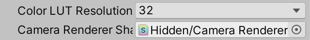
但是现在,当没有激活后处理效果时,渲染失败,因为我们只是渲染到中间缓冲区。我们必须执行最终复制到相机的目标。不幸的是,我们只能使用 CopyTexture 复制到渲染纹理,而不能复制到最终帧缓冲区。我们可以使用后处理效果复制 pass 来完成它,但这一步特定于相机渲染器,因此我们将为其创建一个专用的 CameraRenderer 着色器。它的开始与 PostFX 着色器相同,但只有一个复制 pass,并且它包含自己的 HLSL 文件。
1
2
3
4
5
6
7
8
9
10
11
12
13
14
15
16
17
18
19
20
21
22
Shader "Hidden/Custom RP/Camera Renderer" {
    SubShader {
        Cull Off
        ZTest Always
        ZWrite Off

        HLSLINCLUDE
        #include "../ShaderLibrary/Common.hlsl"
        #include "CameraRendererPasses.hlsl"
        ENDHLSL

        Pass {
            Name "Copy"

            HLSLPROGRAM
                #pragma target 3.5
                #pragma vertex DefaultPassVertex
                #pragma fragment CopyPassFragment
            ENDHLSL
        }
    }
}
新的 CameraRendererPasses HLSL 文件具有与 PostFXStackPasses 相同的 Varyings 结构体和 DefaultPassVertex 函数。它还有一个 _SourceTexture 纹理和一个 CopyPassFragment 函数,该函数简单地返回采样的源纹理。
1
2
3
4
5
6
7
8
9
10
11
12
13
14
#ifndef CUSTOM_CAMERA_RENDERER_PASSES_INCLUDED
#define CUSTOM_CAMERA_RENDERER_PASSES_INCLUDED

TEXTURE2D(_SourceTexture);

struct Varyings { .... };

Varyings DefaultPassVertex (uint vertexID : SV_VertexID) { .... }

float4 CopyPassFragment (Varyings input) : SV_TARGET {
    return SAMPLE_TEXTURE2D_LOD(_SourceTexture, sampler_linear_clamp, input.screenUV, 0);
}

#endif
接下来,向 CameraRenderer 添加一个材质字段。要初始化它,创建一个带有着色器参数的公共构造函数方法,并让它使用着色器作为参数调用 CoreUtils.CreateEngineMaterial。该方法创建一个新材质并将其设置为在编辑器中隐藏,确保它不会被保存为资产,因此我们不必显式地这样做。如果着色器丢失,它还会记录错误。
1
2
3
4
5
Material material;

public CameraRenderer (Shader shader) {
    material = CoreUtils.CreateEngineMaterial(shader);
}
还添加一个公共 Dispose 方法,通过将其传递给 CoreUtils.Destroy 来销毁材质。该方法会根据 Unity 是否处于播放模式来定期或立即销毁材质。我们需要这样做,因为每当修改渲染管线资产时都会创建新的渲染管线实例,从而创建渲染器,这可能导致在编辑器中创建许多材质。
1
2
3
public void Dispose () {
    CoreUtils.Destroy(material);
}
现在 CustomRenderPipeline 必须在构造渲染器时提供一个着色器。所以我们将在它自己的构造函数方法中执行此操作,同时为其添加一个相机渲染器着色器的参数。
1
2
3
4
5
6
7
8
9
10
11
CameraRenderer renderer; // = new CameraRenderer();
....
public CustomRenderPipeline (
    bool allowHDR,
    bool useDynamicBatching, bool useGPUInstancing, bool useSRPBatcher,
    bool useLightsPerObject, ShadowSettings shadowSettings,
    PostFXSettings postFXSettings, int colorLUTResolution, Shader cameraRendererShader
) {
    ....
    renderer = new CameraRenderer(cameraRendererShader);
}
从现在开始,当它自身被释放时,它还必须在渲染器上调用 Dispose。我们已经为它创建了一个 Dispose 方法,但仅用于编辑器代码。将该版本重命名为 DisposeForEditor,并且只让它重置光照贴图委托。
1
2
3
4
5
6
7
8
partial void DisposeForEditor ();

#if UNITY_EDITOR
....
partial void DisposeForEditor () {
    //base.Dispose(disposing);
    Lightmapping.ResetDelegate();
}
然后添加一个新的非仅编辑器的 Dispose 方法,它调用其基础实现、编辑器版本,最后释放渲染器。
1
2
3
4
5
protected override void Dispose (bool disposing) {
    base.Dispose(disposing);
    DisposeForEditor();
    renderer.Dispose();
}
在顶层,CustomRenderPipelineAsset 必须获取一个着色器配置属性并将其传递给管线构造函数。然后我们终于可以连接着色器了。
1
2
3
4
5
6
7
8
9
10
[SerializeField]
Shader cameraRendererShader = default;

protected override RenderPipeline CreatePipeline () {
    return new CustomRenderPipeline(
        allowHDR, useDynamicBatching, useGPUInstancing, useSRPBatcher,
        useLightsPerObject, shadows, postFXSettings, (int)colorLUTResolution,
        cameraRendererShader
    );
}
此时,CameraRenderer 拥有一个可用的材质。还向其添加 _SourceTexture 标识符,并为其提供一个类似于 PostFXStack 中的 Draw 方法,但没有 pass 参数,因为我们目前只有一个 pass。
1
2
3
4
5
6
7
8
9
10
11
12
13
14
15
static int
    colorAttachmentId = Shader.PropertyToID("_CameraColorAttachment"),
    depthAttachmentId = Shader.PropertyToID("_CameraDepthAttachment"),
    depthTextureId = Shader.PropertyToID("_CameraDepthTexture"),
    sourceTextureId = Shader.PropertyToID("_SourceTexture");
....
void Draw (RenderTargetIdentifier from, RenderTargetIdentifier to) {
    buffer.SetGlobalTexture(sourceTextureId, from);
    buffer.SetRenderTarget(
        to, RenderBufferLoadAction.DontCare, RenderBufferStoreAction.Store
    );
    buffer.DrawProcedural(
        Matrix4x4.identity, material, 0, MeshTopology.Triangles, 3
    );
}
要最终修复我们的渲染器,如果后处理效果未激活但我们确实使用了中间缓冲区,则通过调用 Draw 将颜色附件复制到相机目标。
1
2
3
4
5
6
7
if (postFXStack.IsActive) {
    postFXStack.Render(colorAttachmentId);
}
else if (useIntermediateBuffer) {
    Draw(colorAttachmentId, BuiltinRenderTextureType.CameraTarget);
    ExecuteBuffer();
}
重建视图空间深度
要采样深度纹理,我们需要片段的 UV 坐标,它们在屏幕空间中。我们可以通过将其位置除以屏幕像素尺寸来找到它们,Unity 通过 float4 _ScreenParams 的 XY 分量使其可用,因此将其添加到 UnityInput 中。
1
2
3
float4 unity_OrthoParams;
float4 _ProjectionParams;
float4 _ScreenParams;
然后我们可以将片段 UV 和缓冲区深度添加到 Fragment。通过使用点钳位采样器通过 SAMPLE_DEPTH_TEXTURE_LOD 宏采样相机深度纹理来检索缓冲区深度。此宏的功能与 SAMPLE_TEXTURE2D_LOD 相同,但仅返回 R 通道。
1
2
3
4
5
6
7
8
9
10
11
12
13
14
15
16
17
18
19
TEXTURE2D(_CameraDepthTexture);

struct Fragment {
    float2 positionSS;
    float2 screenUV;
    float depth;
    float bufferDepth;
};

Fragment GetFragment (float4 positionCS_SS) {
    Fragment f;
    f.positionSS = positionSS.xy;
    f.screenUV = f.positionSS / _ScreenParams.xy;
    f.depth = IsOrthographicCamera() ?
        OrthographicDepthBufferToLinear(positionSS.z) : positionSS.w;
    f.bufferDepth =
        SAMPLE_DEPTH_TEXTURE_LOD(_CameraDepthTexture, sampler_point_clamp, f.screenUV, 0);
    return f;
}
这为我们提供了原始深度缓冲区值。要将其转换为视图空间深度,在正交相机的情况下,我们可以再次调用 OrthographicDepthBufferToLinear,就像当前片段的深度一样。透视深度也必须转换,为此我们可以使用 LinearEyeDepth。它需要 _ZBufferParams 作为第二个参数。
1
2
3
4
f.bufferDepth = LOAD_TEXTURE2D(_CameraDepthTexture, f.positionSS).r;
f.bufferDepth = IsOrthographicCamera() ?
    OrthographicDepthBufferToLinear(f.bufferDepth) :
    LinearEyeDepth(f.bufferDepth, _ZBufferParams);
_ZBufferParams 是 Unity 提供的另一个 float4,它包含从原始深度到线性深度的转换因子。将其添加到 UnityInput。
1
2
3
4
float4 unity_OrthoParams;
float4 _ProjectionParams;
float4 _ScreenParams;
float4 _ZBufferParams;
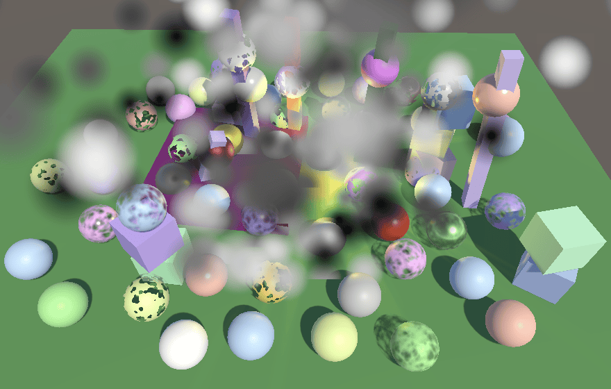
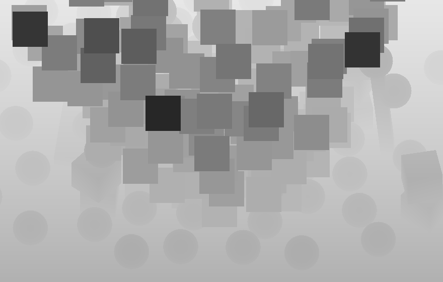
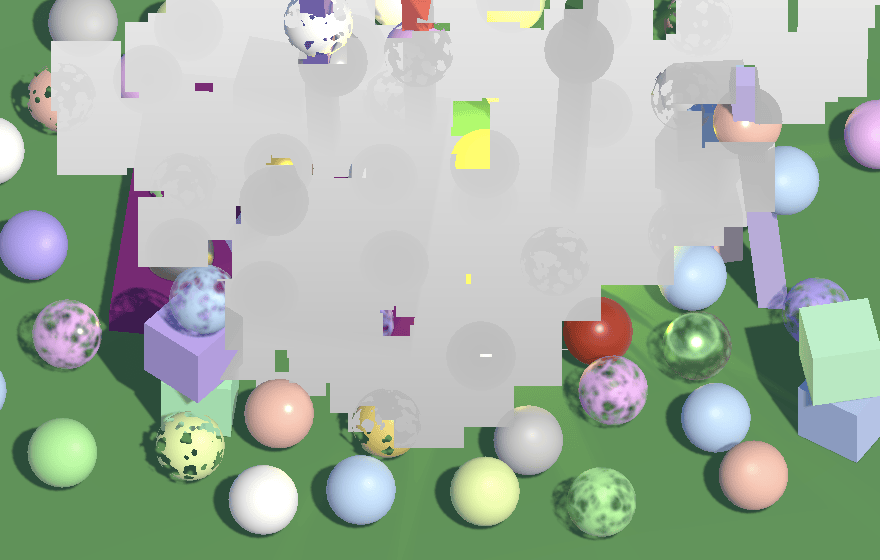
要检查我们是否正确采样了缓冲区深度,请在 UnlitPassFragment 中返回它的缩放版本,就像我们之前测试片段深度一样。
1
2
InputConfig config = GetInputConfig(input.positionCS_SS, input.baseUV);
return float4(config.fragment.bufferDepth.xxx / 20.0, 1.0);
一旦明确采样的深度是正确的,就删除调试可视化。
1
//return float4(config.fragment.bufferDepth.xxx / 20.0, 1.0);
可选的深度纹理
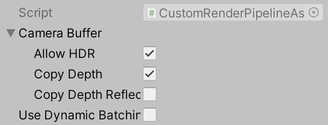
复制深度需要额外的工作,尤其是在不使用后处理效果时,因为这还需要中间缓冲区和对相机目标的额外复制。因此,让我们将渲染管线是否支持复制深度设置为可配置的。我们将为此创建一个新的 CameraBufferSettings 结构体,放在其自己的文件中,用于分组所有与相机缓冲区相关的设置。除了复制深度的切换外,还将允许 HDR 的切换放在其中。还引入一个单独的切换来控制渲染反射时是否复制深度。这很有用,因为反射是在没有后处理效果的情况下渲染的,粒子系统也不会出现在反射中,因此为反射复制深度既昂贵又可能无用。我们确实使其成为可能,因为深度也可以用于其他效果,这些效果可能在反射中可见。即便如此,请记住,深度缓冲区对于每个立方体贴图反射面都是不同的,因此沿着立方体贴图边缘会有深度接缝。
1
2
3
4
5
[System.Serializable]
public struct CameraBufferSettings {
    public bool allowHDR;
    public bool copyDepth, copyDepthReflections;
}
将 CustomRenderPipelineAsset 的当前 HDR 切换替换为这些相机缓冲区设置。
1
2
3
4
5
6
7
8
9
10
11
12
13
14
15
//[SerializeField]
//bool allowHDR = true;

[SerializeField]
CameraBufferSettings cameraBuffer = new CameraBufferSettings {
    allowHDR = true
};

protected override RenderPipeline CreatePipeline () {
    return new CustomRenderPipeline(
        cameraBuffer, useDynamicBatching, useGPUInstancing, useSRPBatcher,
        useLightsPerObject, shadows, postFXSettings, (int)colorLUTResolution,
        cameraRendererShader
    );
}
也将更改应用到 CustomRenderPipeline。
1
2
3
4
5
6
7
8
9
10
11
12
13
14
15
16
17
18
19
20
21
22
23
24
25
26
//bool allowHDR;
CameraBufferSettings cameraBufferSettings;
....
public CustomRenderPipeline (
    CameraBufferSettings cameraBufferSettings,
    bool useDynamicBatching, bool useGPUInstancing, bool useSRPBatcher,
    bool useLightsPerObject, ShadowSettings shadowSettings,
    PostFXSettings postFXSettings, int colorLUTResolution, Shader cameraRendererShader
) {
    this.colorLUTResolution = colorLUTResolution;
    //this.allowHDR = allowHDR;
    this.cameraBufferSettings = cameraBufferSettings;
    ....
}
....
protected override void Render (
    ScriptableRenderContext context, List<Camera> cameras
) {
    for (int i = 0; i < cameras.Count; i++) {
        renderer.Render(
            context, cameras[i], cameraBufferSettings,
            useDynamicBatching, useGPUInstancing, useLightsPerObject,
            shadowSettings, postFXSettings, colorLUTResolution
        );
    }
}
CameraRenderer.Render 现在必须根据是否正在渲染反射来使用适当的设置。
1
2
3
4
5
6
7
8
9
10
11
12
13
14
15
16
17
18
19
public void Render (
    ScriptableRenderContext context, Camera camera,
    CameraBufferSettings bufferSettings,
    bool useDynamicBatching, bool useGPUInstancing, bool useLightsPerObject,
    ShadowSettings shadowSettings, PostFXSettings postFXSettings,
    int colorLUTResolution
) {
    ....
    //useDepthTexture = true;
    if (camera.cameraType == CameraType.Reflection) {
        useDepthTexture = bufferSettings.copyDepthReflection;
    }
    else {
        useDepthTexture = bufferSettings.copyDepth;
    }
    ....
    useHDR = bufferSettings.allowHDR && camera.allowHDR;
    ....
}
除了整个渲染管线的设置之外,我们还可以向 CameraSettings 添加一个复制深度切换,默认启用。
1
public bool copyDepth = true;
然后对于常规相机,仅当渲染管线和相机都启用了深度纹理时才使用深度纹理,类似于 HDR 的控制方式。
1
2
3
4
5
6
if (camera.cameraType == CameraType.Reflection) {
    useDepthTexture = bufferSettings.copyDepthReflection;
}
else {
    useDepthTexture = bufferSettings.copyDepth && cameraSettings.copyDepth;
}
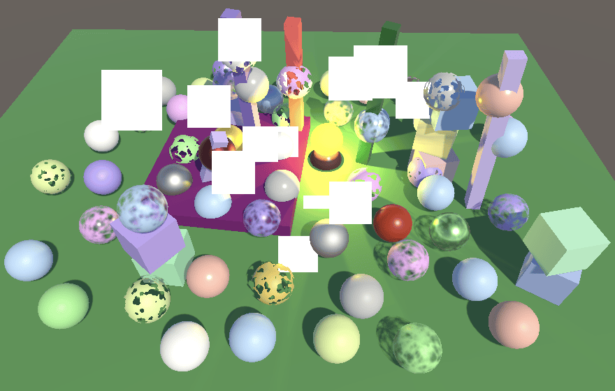
缺失的纹理
由于深度纹理是可选的,它可能不存在。当着色器无论如何采样它时,结果将是随机的。它可能是一个空纹理或一个旧副本,可能是另一个相机的。着色器也可能在不透明渲染阶段过早地采样深度纹理。我们至少可以做的是确保无效采样将产生一致的结果。我们通过在 CameraRenderer 的构造函数方法中创建一个默认的缺失纹理来做到这一点。没有用于纹理的 CoreUtils 方法,因此我们将自己将其隐藏标志设置为 HideFlags.HideAndDontSave。将其命名为 Missing,以便在通过帧调试器检查着色器属性时很明显使用了错误的纹理。使其成为一个简单的 1×1 纹理,所有通道都设置为 0.5。还在渲染器被释放时适当地销毁它。
1
2
3
4
5
6
7
8
9
10
11
12
13
14
15
16
Texture2D missingTexture;

public CameraRenderer (Shader shader) {
    material = CoreUtils.CreateEngineMaterial(shader);
    missingTexture = new Texture2D(1, 1) {
        hideFlags = HideFlags.HideAndDontSave,
        name = "Missing"
    };
    missingTexture.SetPixel(0, 0, Color.white * 0.5f);
    missingTexture.Apply(true, true);
}

public void Dispose () {
    CoreUtils.Destroy(material);
    CoreUtils.Destroy(missingTexture);
}
在 Setup 结束时使用缺失纹理作为深度纹理。
1
2
3
4
5
6
void Setup () {
    ....
    buffer.BeginSample(SampleName);
    buffer.SetGlobalTexture(depthTextureId, missingTexture);
    ExecuteBuffer();
}
淡化背景附近的粒子
现在我们有了一个可用的深度纹理,我们可以继续最终支持软粒子。第一步是向 UnlitParticles 添加软粒子关键字切换、距离和范围的着色器属性,类似于近距离淡出属性。在这种情况下,距离是从粒子后面的任何物体开始测量的,因此我们默认将其设置为零。
1
2
3
[Toggle(_SOFT_PARTICLES)] _SoftParticles ("Soft Particles", Float) = 0
_SoftParticlesDistance ("Soft Particles Distance", Range(0.0, 10.0)) = 0
_SoftParticlesRange ("Soft Particles Range", Range(0.01, 10.0)) = 1
也为其添加着色器特性。
1
#pragma shader_feature _SOFT_PARTICLES
与近距离淡出类似,如果定义了关键字,则在 UnlitPassFragment 中将适当的配置字段设置为 true。
1
2
3
4
5
6
#if defined(_NEAR_FADE)
    config.nearFade = true;
#endif
#if defined(_SOFT_PARTICLES)
    config.softParticles = true;
#endif
在 UnlitInput 中,将新的着色器属性添加到 UnityPerMaterial,并将字段添加到 InputConfig。
1
2
3
4
5
6
7
8
9
10
11
12
13
14
15
16
17
18
19
20
UNITY_INSTANCING_BUFFER_START(UnityPerMaterial)
    ....
    UNITY_DEFINE_INSTANCED_PROP(float, _SoftParticlesDistance)
    UNITY_DEFINE_INSTANCED_PROP(float, _SoftParticlesRange)
    UNITY_DEFINE_INSTANCED_PROP(float, _Cutoff)
    UNITY_DEFINE_INSTANCED_PROP(float, _ZWrite)
UNITY_INSTANCING_BUFFER_END(UnityPerMaterial)

#define INPUT_PROP(name) UNITY_ACCESS_INSTANCED_PROP(UnityPerMaterial, name)

struct InputConfig {
    ....
    bool softParticles;
};

InputConfig GetInputConfig (float4 positionCC_SS, float2 baseUV) {
    ....
    c.softParticles = false;
    return c;
}
然后在 GetBase 中应用另一个近距离衰减,这次基于片段的缓冲区深度减去其自身深度。
1
2
3
4
5
6
7
8
9
10
11
12
if (c.nearFade) {
    float nearAttenuation = (c.fragment.depth - INPUT_PROP(_NearFadeDistance)) /
        INPUT_PROP(_NearFadeRange);
    baseMap.a *= saturate(nearAttenuation);
}

if (c.softParticles) {
    float depthDelta = c.fragment.bufferDepth - c.fragment.depth;
    float nearAttenuation = (depthDelta - INPUT_PROP(_SoftParticlesDistance)) /
        INPUT_PROP(_SoftParticlesRange);
    baseMap.a *= saturate(nearAttenuation);
}

不支持纹理复制
这一切都工作得很好,但仅在支持通过 CopyTexture 直接复制纹理的情况下,至少在基本级别上。这主要是这种情况,但对于 WebGL 2.0 则不是。因此,如果我们也想支持 WebGL 2.0,我们必须回退到通过着色器复制,这效率较低,但至少可以工作。
通过 CameraRenderer 中的静态布尔字段跟踪是否支持 CopyTexture。最初将其设置为 false,这样即使我们的开发机器都支持它,我们也可以测试回退方法。
1
static bool copyTextureSupported = false;
在 CopyAttachments 中,如果支持,则通过 CopyTexture 复制深度,否则回退到使用我们的 Draw 方法。
1
2
3
4
5
6
7
8
9
10
11
12
13
14
15
void CopyAttachments () {
    if (useDepthTexture) {
        buffer.GetTemporaryRT(
            depthTextureId, camera.pixelWidth, camera.pixelHeight,
            32, FilterMode.Point, RenderTextureFormat.Depth
        );
        if (copyTextureSupported) {
            buffer.CopyTexture(depthAttachmentId, depthTextureId);
        }
        else {
            Draw(depthAttachmentId, depthTextureId);
        }
        ExecuteBuffer();
    }
}
这最初未能产生正确的结果,因为 Draw 更改了渲染目标,因此进一步的绘制出错了。我们必须在之后将渲染目标设置回相机缓冲区,再次加载我们的附件。
1
2
3
4
5
6
7
8
9
10
11
12
if (copyTextureSupported) {
    buffer.CopyTexture(depthAttachmentId, depthTextureId);
}
else {
    Draw(depthAttachmentId, depthTextureId);
    buffer.SetRenderTarget(
        colorAttachmentId,
        RenderBufferLoadAction.Load, RenderBufferStoreAction.Store,
        depthAttachmentId,
        RenderBufferLoadAction.Load, RenderBufferStoreAction.Store
    );
}
第二个出错的是深度根本没有被复制,因为我们的复制 pass 只写入默认着色器目标,这是针对颜色数据的,而不是深度。要复制深度,我们需要向 CameraRenderer 着色器添加第二个 copy-depth pass,该 pass 写入深度而不是颜色。我们通过将其 ColorMask 设置为零并打开 ZWrite 来做到这一点。它还需要一个特殊的片段函数,我们将其命名为 CopyDepthPassFragment。
1
2
3
4
5
6
7
8
9
10
11
12
Pass {
    Name "Copy Depth"

    ColorMask 0
    ZWrite On

    HLSLPROGRAM
        #pragma target 3.5
        #pragma vertex DefaultPassVertex
        #pragma fragment CopyDepthPassFragment
    ENDHLSL
}
新的片段函数必须采样深度并将其作为带有 SV_DEPTH 语义的单个 float 返回,而不是带有 SV_TARGET 语义的 float4。这样我们采样原始深度缓冲区值并直接将其用于片段的新深度。
1
2
3
4
5
6
7
float4 CopyPassFragment (Varyings input) : SV_TARGET {
    return SAMPLE_TEXTURE2D_LOD(_SourceTexture, sampler_linear_clamp, input.screenUV, 0);
}

float CopyDepthPassFragment (Varyings input) : SV_DEPTH {
    return SAMPLE_DEPTH_TEXTURE_LOD(_SourceTexture, sampler_point_clamp, input.screenUV, 0);
}
接下来,回到 CameraRenderer 并向 Draw 添加一个布尔参数,以指示我们是从深度绘制到深度,默认设置为 false。如果是,则使用第二个 pass 而不是第一个 pass。
1
2
3
4
5
6
7
8
public void Draw (
    RenderTargetIdentifier from, RenderTargetIdentifier to, bool isDepth = false
) {
    ....
    buffer.DrawProcedural(
        Matrix4x4.identity, material, isDepth ? 1 : 0, MeshTopology.Triangles, 3
    );
}
然后在复制深度缓冲区时指示我们正在使用深度。
1
Draw(depthAttachmentId, depthTextureId, true);
在验证此方法也有效后,通过检查 SystemInfo.copyTextureSupport 来确定是否支持 CopyTexture。任何大于 none 的支持级别都足够了。
1
2
static bool copyTextureSupported =
    SystemInfo.copyTextureSupport > CopyTextureSupport.None;
Gizmos 和深度
现在我们有了绘制深度的方法,我们可以在结合后处理效果或使用深度纹理时再次使其 gizmos 具有深度感知能力。在 DrawGizmosBeforeFX 中,在绘制第一个 gizmos 之前,如果我们使用中间缓冲区,则将深度复制到相机目标。
1
2
3
4
5
6
7
8
9
partial void DrawGizmosBeforeFX () {
    if (Handles.ShouldRenderGizmos()) {
        if (useIntermediateBuffer) {
            Draw(depthAttachmentId, BuiltinRenderTextureType.CameraTarget, true);
            ExecuteBuffer();
        }
        context.DrawGizmos(camera, GizmoSubset.PreImageEffects);
    }
}
如果使用后处理效果,我们也必须再次这样做。
1
2
3
4
5
6
7
8
9
10
partial void DrawGizmosAfterFX () {
    if (Handles.ShouldRenderGizmos()) {
        if (postFXStack.IsActive)
        {
            Draw(depthAttachmentId, BuiltinRenderTextureType.CameraTarget, true);
            ExecuteBuffer();
        }
        context.DrawGizmos(camera, GizmoSubset.PostImageEffects);
    }
}
扭曲效果
我们还将支持 Unity 粒子的另一个功能是扭曲,它可以用来创建像热量引起的大气折射这样的效果。这需要对颜色缓冲区进行采样,就像我们已经采样深度缓冲区一样,但需要添加 UV 偏移。
颜色复制纹理
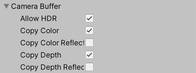
我们首先向 CameraBufferSettings 添加复制颜色的切换,同样为常规相机和反射相机分别设置一个。
1
public bool copyColor, copyColorReflection, copyDepth, copyDepthReflection;
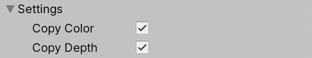
也使每个相机的复制颜色可配置。
1
public bool copyColor = true, copyDepth = true;
CameraRenderer 现在还必须跟踪颜色纹理的标识符以及是否使用颜色纹理。
1
2
3
4
5
6
7
8
9
10
11
12
13
14
15
16
17
18
colorTextureId = Shader.PropertyToID("_CameraColorTexture"),
depthTextureId = Shader.PropertyToID("_CameraDepthTexture"),
sourceTextureId = Shader.PropertyToID("_SourceTexture");
....
bool useColorTexture, useDepthTexture, useIntermediateBuffer;
....
public void Render (....) {
    ....
    if (camera.cameraType == CameraType.Reflection) {
        useColorTexture = bufferSettings.copyColorReflection;
        useDepthTexture = bufferSettings.copyDepthReflection;
    }
    else {
        useColorTexture = bufferSettings.copyColor && cameraSettings.copyColor;
        useDepthTexture = bufferSettings.copyDepth && cameraSettings.copyDepth;
    }
    ....
}
我们是否使用中间缓冲区现在还取决于是否使用颜色纹理。我们还应该最初将颜色纹理设置为缺失纹理。在清理时也释放它。
1
2
3
4
5
6
7
8
9
10
11
12
13
14
15
16
17
18
19
20
21
22
23
24
void Setup () {
    ....
    useIntermediateBuffer =
        useColorTexture || useDepthTexture || postFXStack.IsActive;
    ....
    buffer.BeginSample(SampleName);
    buffer.SetGlobalTexture(colorTextureId, missingTexture);
    buffer.SetGlobalTexture(depthTextureId, missingTexture);
    ExecuteBuffer();
}

void Cleanup () {
    lighting.Cleanup();
    if (useIntermediateBuffer) {
        buffer.ReleaseTemporaryRT(colorAttachmentId);
        buffer.ReleaseTemporaryRT(depthAttachmentId);
        if (useColorTexture) {
            buffer.ReleaseTemporaryRT(colorTextureId);
        }
        if (useDepthTexture) {
            buffer.ReleaseTemporaryRT(depthTextureId);
        }
    }
}
我们现在需要在使用颜色或深度纹理或两者时复制相机附件。让我们使 CopyAttachments 的调用依赖于此。
1
2
3
4
context.DrawSkybox(camera);
if (useColorTexture || useDepthTexture) {
    CopyAttachments();
}
然后我们可以让它分别复制两个纹理,之后重置渲染目标并执行一次缓冲区。
1
2
3
4
5
6
7
8
9
10
11
12
13
14
15
16
17
18
19
20
21
22
23
24
25
26
27
28
29
30
31
32
33
34
35
36
37
38
39
void CopyAttachments () {
    if (useColorTexture) {
        buffer.GetTemporaryRT(
            colorTextureId, camera.pixelWidth, camera.pixelHeight,
            0, FilterMode.Bilinear, useHDR ?
                RenderTextureFormat.DefaultHDR : RenderTextureFormat.Default
        );
        if (copyTextureSupported) {
            buffer.CopyTexture(colorAttachmentId, colorTextureId);
        }
        else {
            Draw(colorAttachmentId, colorTextureId);
        }
    }
    if (useDepthTexture) {
        buffer.GetTemporaryRT(
            depthTextureId, camera.pixelWidth, camera.pixelHeight,
            32, FilterMode.Point, RenderTextureFormat.Depth
        );
        if (copyTextureSupported) {
            buffer.CopyTexture(depthAttachmentId, depthTextureId);
        }
        else {
            Draw(depthAttachmentId, depthTextureId, true);
            //buffer.SetRenderTarget(....);
        }
        //ExecuteBuffer();
    }

    if (!copyTextureSupported) {
        buffer.SetRenderTarget(
            colorAttachmentId,
            RenderBufferLoadAction.Load, RenderBufferStoreAction.Store,
            depthAttachmentId,
            RenderBufferLoadAction.Load, RenderBufferStoreAction.Store
        );
    }
    ExecuteBuffer();
}
采样缓冲区颜色
要采样相机颜色纹理,请将其添加到 Fragment。我们不会向 Fragment 添加缓冲区颜色属性,因为我们对其精确位置的颜色不感兴趣。相反,我们引入一个 GetBufferColor 函数,它接受一个片段和 UV 偏移作为参数,返回采样的颜色。
1
2
3
4
5
6
7
8
9
10
11
TEXTURE2D(_CameraColorTexture);
TEXTURE2D(_CameraDepthTexture);

struct Fragment { .... };

Fragment GetFragment (float4 positionCS_SS) { .... }

float4 GetBufferColor (Fragment fragment, float2 uvOffset = float2(0.0, 0.0)) {
    float2 uv = fragment.screenUV + uvOffset;
    return SAMPLE_TEXTURE2D_LOD(_CameraColorTexture, sampler_linear_clamp, uv, 0);
}
要测试这一点,在 UnlitPassFragment 中返回带有小偏移(如两个维度各 5%)的缓冲区颜色。
1
2
InputConfig config = GetInputConfig(input.positionCS_SS, input.baseUV);
return GetBufferColor(config.fragment, 0.05);
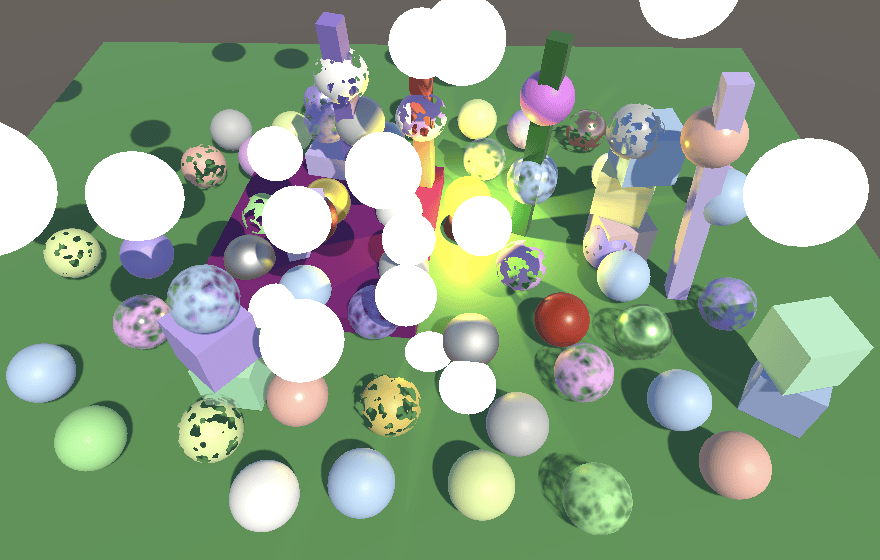
请注意,由于颜色在不透明阶段之后被复制,因此透明对象从中丢失。因此,粒子会擦除在它们之前绘制的所有透明对象,包括彼此。同时,深度在这种情况下不起作用,因此比片段本身更靠近相机平面的片段的颜色也会被复制。
当确认它工作正常时,删除调试可视化。
1
//return GetBufferColor(config.fragment, 0.05);
扭曲向量
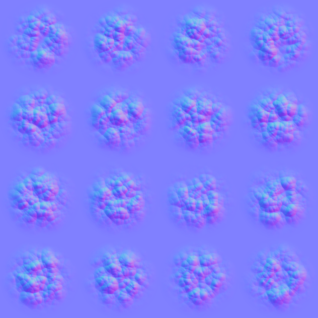
要创建有用的扭曲效果,我们需要一个平滑过渡的扭曲向量贴图。这是一个简单的单个圆形粒子的贴图。它是一个法线贴图,因此将其导入为法线贴图。
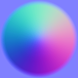
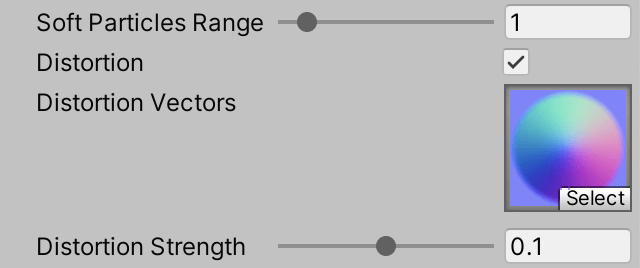
向 UnlitParticles 添加关键字切换着色器属性,以及扭曲贴图和强度属性。扭曲将作为屏幕空间 UV 偏移应用,因此需要小值。让我们使用 0-0.2 的强度范围,默认值为 0.1。
1
2
3
[Toggle(_DISTORTION)] _Distortion ("Distortion", Float) = 0
[NoScaleOffset] _DistortionMap("Distortion Vectors", 2D) = "bumb" {}
_DistortionStrength("Distortion Strength", Range(0.0, 0.2)) = 0.1
添加所需的着色器特性。
1
#pragma shader_feature _DISTORTION
然后将扭曲贴图和强度属性添加到 UnlitInput。
1
2
3
4
5
6
7
8
9
10
TEXTURE2D(_BaseMap);
TEXTURE2D(_DistortionMap);
SAMPLER(sampler_BaseMap);

UNITY_INSTANCING_BUFFER_START(UnityPerMaterial)
    ....
    UNITY_DEFINE_INSTANCED_PROP(float, _SoftParticlesRange)
    UNITY_DEFINE_INSTANCED_PROP(float, _DistortionStrength)
    ....
UNITY_INSTANCING_BUFFER_END(UnityPerMaterial)
引入一个新的 GetDistortion 函数,返回一个 float2 向量。让它采样扭曲贴图并像基础贴图一样应用翻书混合,然后解码按扭曲强度缩放的法线。我们只需要向量的 XY 分量,因此丢弃 Z。
1
2
3
4
5
6
7
8
9
10
float2 GetDistortion (InputConfig c) {
    float4 rawMap = SAMPLE_TEXTURE2D(_DistortionMap, sampler_BaseMap, c.baseUV);
    if (c.flipbookBlending) {
        rawMap = lerp(
            rawMap, SAMPLE_TEXTURE2D(_DistortionMap, sampler_BaseMap, c.flipbookUVB.xy),
            c.flipbookUVB.z
        );
    }
    return DecodeNormal(rawMap, INPUT_PROP(_DistortionStrength)).xy;
}
在 UnlitPassFragment 中,如果启用了扭曲,则检索它并将其用作偏移来获取缓冲区颜色,覆盖基础颜色。在裁剪之后执行此操作。
1
2
3
4
5
6
7
8
9
float4 base = GetBase(config);
#if defined(_CLIPPING)
    clip(base.a - GetCutoff(config));
#endif

#if defined(_DISTORTION)
    float2 distortion = GetDistortion(config);
    base = GetBufferColor(config.fragment, distortion);
#endif
结果是粒子径向扭曲颜色纹理,除了它们的角落,因为那里的扭曲向量为零。但扭曲效果应该取决于粒子的视觉强度,这由原始基础 alpha 控制。因此用基础 alpha 调制扭曲偏移向量。
1
float2 distortion = GetDistortion(config) * base.a;
此时我们仍然得到硬边缘,暴露了粒子完全重叠并且是矩形的。我们通过保持粒子的原始 alpha 来隐藏这一点。
1
base.rgb = GetBufferColor(config.fragment, distortion).rgb;
现在扭曲的颜色纹理样本也会淡出,这使得未扭曲的背景和其他粒子部分可见。结果是一个平滑的混乱,在物理上没有意义,但足以提供大气折射的错觉。这可以通过调整扭曲强度以及通过在粒子的生命周期内调整它们的颜色来平滑地淡入淡出粒子来进一步改进。此外,偏移向量与屏幕对齐,不受粒子方向的影响。因此,如果粒子设置为在其生命周期内旋转,它们的单个扭曲模式将看起来会扭曲。
扭曲混合
目前,当启用扭曲时,我们完全替换粒子的原始颜色,只保留它们的 alpha。粒子颜色可以以各种方式与扭曲的颜色缓冲区组合。我们将添加一个简单的扭曲混合着色器属性,以在粒子自己的颜色和它引起的扭曲之间进行插值,使用与 Unity 粒子着色器相同的方法。
1
2
_DistortionStrength("Distortion Strength", Range(0.0, 0.2)) = 0.1
_DistortionBlend("Distortion Blend", Range(0.0, 1.0)) = 1
将属性添加到 UnlitInput 以及一个函数来获取它。
1
2
3
4
5
6
UNITY_DEFINE_INSTANCED_PROP(float, _DistortionStrength)
UNITY_DEFINE_INSTANCED_PROP(float, _DistortionBlend)
....
float GetDistortionBlend (InputConfig c) {
    return INPUT_PROP(_DistortionBlend);
}
其思想是,当混合滑块为 1 时,我们只看到扭曲。降低它会使粒子颜色出现,但它不会完全隐藏扭曲。相反,我们根据其 alpha 减去混合滑块(饱和后)从扭曲插值到粒子颜色。因此,当启用扭曲时,粒子自己的颜色将始终更弱,并且与禁用扭曲时相比显得更小,除非它完全不透明的地方。在 UnlitPassFragment 中执行插值。
1
2
3
4
5
6
7
#if defined(_DISTORTION)
    float2 distortion = GetDistortion(config) * base.a;
    base.rgb = lerp(
        GetBufferColor(config.fragment, distortion).rgb, base.rgb,
        saturate(base.a - GetDistortionBlend(config))
    );
#endif
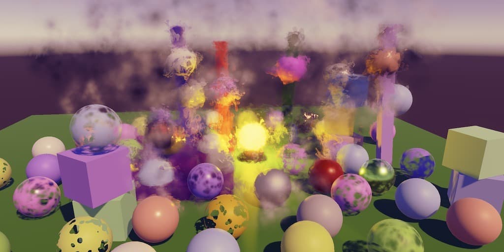
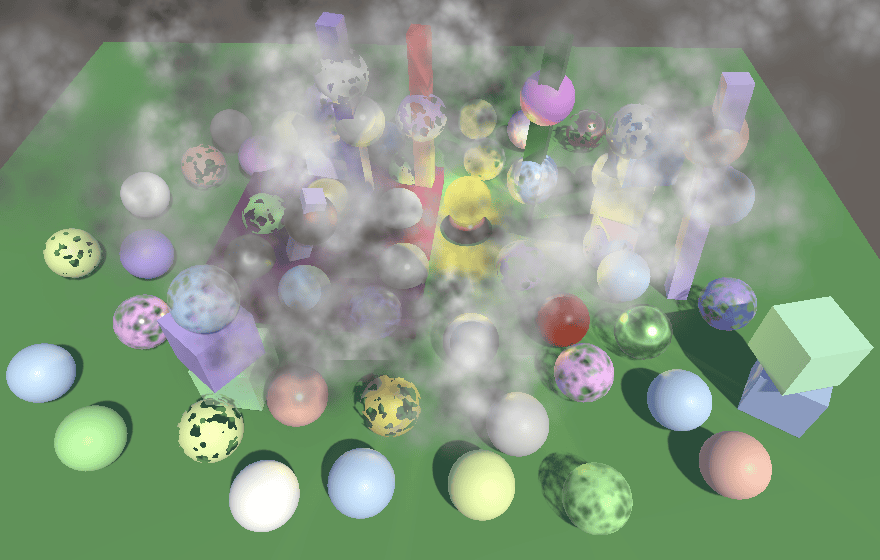
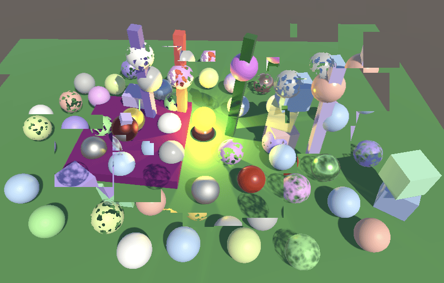
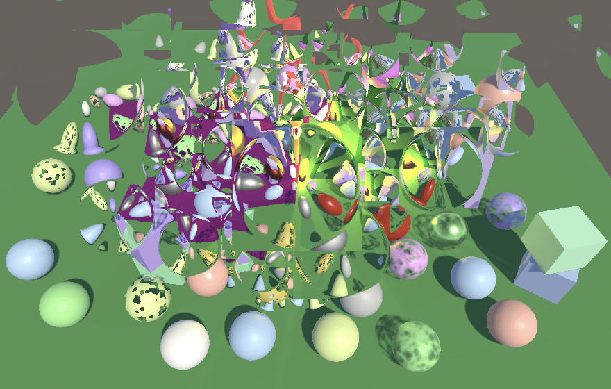
这对于更复杂的粒子(如我们的翻书示例)看起来更好。因此,这是翻书的扭曲纹理。
这可以用来创建有趣的扭曲效果。逼真的效果会很微妙,因为当系统处于运动状态时,一点扭曲就足够了。但出于演示目的,我将效果做得很强,以便它们在视觉上很明显,即使在截图中也是如此。
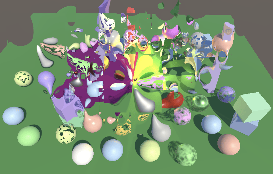
带有翻书和后处理效果的扭曲
修复非标准相机
我们当前的方法在仅使用单个相机时有效,但在没有后处理效果的情况下渲染到中间纹理时会失败。这是因为我们正在执行到相机目标的常规复制,这会忽略视口和最终混合模式。因此,CameraRenderer 也需要一个 FinalPass 方法。它是 PostFXStack.FinalPass 的副本,只是我们将使用常规复制 pass,因此我们应该在之后将混合模式设置回 one-zero,以免影响其他复制操作。源纹理始终是颜色附件,最终混合模式成为参数。
同样,对于 Unity 2022,如果我们不渲染到完整视口,我们确实关心加载缓冲区。
1
2
3
4
5
6
7
8
9
10
11
12
13
14
15
16
17
18
19
static Rect fullViewRect = new Rect(0f, 0f, 1f, 1f);
....
void DrawFinal (CameraSettings.FinalBlendMode finalBlendMode) {
    buffer.SetGlobalFloat(srcBlendId, (float)finalBlendMode.source);
    buffer.SetGlobalFloat(dstBlendId, (float)finalBlendMode.destination);
    buffer.SetGlobalTexture(sourceTextureId, colorAttachmentId);
    buffer.SetRenderTarget(
        BuiltinRenderTextureType.CameraTarget,
        finalBlendMode.destination == BlendMode.Zero && camera.rect == fullViewRect?
            RenderBufferLoadAction.DontCare : RenderBufferLoadAction.Load,
        RenderBufferStoreAction.Store
    );
    buffer.SetViewport(camera.pixelRect);
    buffer.DrawProcedural(
        Matrix4x4.identity, material, 0, MeshTopology.Triangles, 3
    );
    buffer.SetGlobalFloat(srcBlendId, 1f);
    buffer.SetGlobalFloat(dstBlendId, 0f);
}
在这种情况下,我们将混合模式着色器属性命名为 _CameraSrcBlend 和 _CameraDstBlend。
1
2
3
sourceTextureId = Shader.PropertyToID("_SourceTexture"),
srcBlendId = Shader.PropertyToID("_CameraSrcBlend"),
dstBlendId = Shader.PropertyToID("_CameraDstBlend");
调整 CameraRenderer 的复制 pass 以依赖这些属性。
1
2
3
4
5
6
7
8
9
10
11
Pass {
    Name "Copy"

    Blend [_CameraSrcBlend] [_CameraDstBlend]

    HLSLPROGRAM
        #pragma target 3.5
        #pragma vertex DefaultPassVertex
        #pragma fragment CopyPassFragment
    ENDHLSL
}
最后,在 Render 中调用 DrawFinal 而不是 Draw。
1
2
3
4
5
6
7
if (postFXStack.IsActive) {
    postFXStack.Render(colorAttachmentId);
}
else if (useIntermediateBuffer) {
    DrawFinal(cameraSettings.finalBlendMode);
    ExecuteBuffer();
}
请注意,颜色和深度纹理仅包含当前相机渲染的内容。扭曲粒子和类似效果不会拾取其他相机的数据。
下一个文章Render Scale