自定义渲染管线:后处理 (翻译十一)
创建简单的后处理栈,实现艺术性的泛光效果
- 创建一个简单的后期特效堆栈。
- 修改渲染图像。
- 根据需要进行后期处理。
- 制作艺术性的光晕效果。
后处理栈
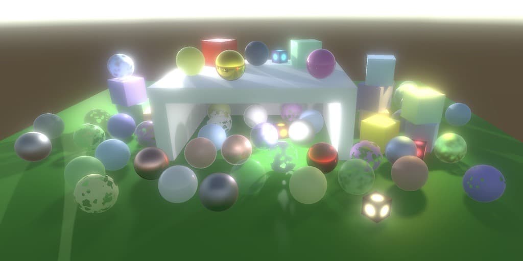
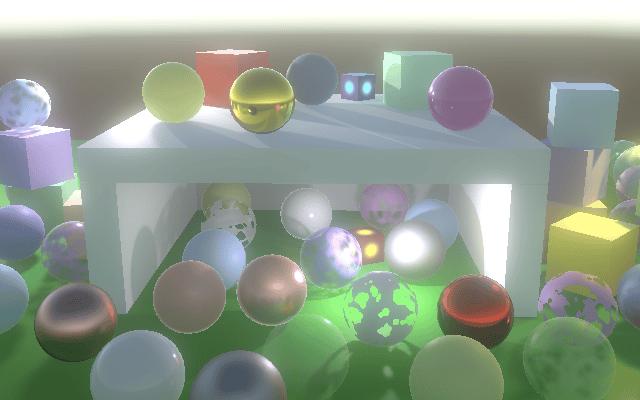
大多数时候,渲染后的图像不会原样显示。图像会经过后处理,应用各种效果(简称 FX)。常见的 FX 包括泛光(bloom)、颜色分级(color grading)、景深(depth-of-field)、运动模糊(motion blur)和色调映射(tone mapping)。这些 FX 以栈的形式应用,一个接一个。在本教程中,我们将创建一个简单的后处理栈,最初只支持泛光效果。
设置资产
一个项目可能需要多个后处理栈配置,所以我们首先创建一个 PostFXSettings 资产类型来存储栈的设置。
1
2
3
4
using UnityEngine;

[CreateAssetMenu(menuName = "Rendering/Custom Post FX Settings")]
public class PostFXSettings : ScriptableObject { }
在本教程中,我们将使用单个栈,通过向 CustomRenderPipelineAsset 添加配置选项,使其可用于 RP,并将其传递给 RP 的构造函数。
1
2
3
4
5
6
7
8
9
[SerializeField]
PostFXSettings postFXSettings = default;

protected override RenderPipeline CreatePipeline () {
    return new CustomRenderPipeline(
        useDynamicBatching, useGPUInstancing, useSRPBatcher,
        useLightsPerObject, shadows, postFXSettings
    );
}
然后,CustomRenderPipeline 必须跟踪 FX 设置,并在渲染期间将它们与其他设置一起传递给摄像机渲染器。
1
2
3
4
5
6
7
8
9
10
11
12
13
14
15
16
17
18
19
20
21
22
PostFXSettings postFXSettings;

public CustomRenderPipeline (
    bool useDynamicBatching, bool useGPUInstancing, bool useSRPBatcher,
    bool useLightsPerObject, ShadowSettings shadowSettings,
    PostFXSettings postFXSettings
) {
    this.postFXSettings = postFXSettings;
    ...
}

protected override void Render (
    ScriptableRenderContext context, Camera[] cameras
) {
    foreach (Camera camera in cameras) {
        renderer.Render(
            context, camera,
            useDynamicBatching, useGPUInstancing, useLightsPerObject,
            shadowSettings, postFXSettings
        );
    }
}
CameraRenderer.Render 最初不对设置做任何处理,因为我们还没有栈。
1
2
3
4
5
public void Render (
    ScriptableRenderContext context, Camera camera,
    bool useDynamicBatching, bool useGPUInstancing, bool useLightsPerObject,
    ShadowSettings shadowSettings, PostFXSettings postFXSettings
) { ... }
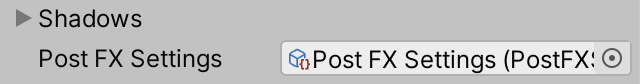
现在我们可以创建一个空的后处理设置资产,并将其分配给管线资产。
栈对象
我们将使用与 Lighting 和 Shadows 相同的方法来处理栈。我们为其创建一个类,该类跟踪缓冲区、上下文、摄像机和后处理 FX 设置,并提供一个公共的 Setup 方法来初始化它们。
1
2
3
4
5
6
7
8
9
10
11
12
13
14
15
16
17
18
19
20
21
22
using UnityEngine;
using UnityEngine.Rendering;

public class PostFXStack {
    const string bufferName = "Post FX";

    CommandBuffer buffer = new CommandBuffer {
        name = bufferName
    };

    ScriptableRenderContext context;
    Camera camera;
    PostFXSettings settings;

    public void Setup (
        ScriptableRenderContext context, Camera camera, PostFXSettings settings
    ) {
        this.context = context;
        this.camera = camera;
        this.settings = settings;
    }
}
接下来,添加一个公共属性来指示栈是否处于活动状态,只有在有设置时才会处于活动状态。这意味着如果没有提供设置,应跳过后处理。
1
public bool IsActive => settings != null;
我们需要的最后一部分是一个公共的 Render 方法来渲染栈。将效果应用于整个图像的方法是使用适当的着色器简单地绘制覆盖整个图像的矩形。现在我们还没有着色器,所以我们只需将到目前为止渲染的内容复制到摄像机的帧缓冲区。这可以通过在命令缓冲区上调用 Blit 来完成,为其传递源和目标的标识符。这些标识符可以以多种格式提供。我们将使用整数作为源(为此添加一个参数),并使用 BuiltinRenderTextureType.CameraTarget 作为目标。然后执行并清除缓冲区。
1
2
3
4
5
public void Render (int sourceId) {
    buffer.Blit(sourceId, BuiltinRenderTextureType.CameraTarget);
    context.ExecuteCommandBuffer(buffer);
    buffer.Clear();
}
在这种情况下,我们不需要手动开始和结束缓冲区采样,因为我们不需要调用 ClearRenderTarget,因为我们完全替换了目标处的内容。
使用栈
CameraRenderer 现在需要一个栈实例,并在 Render 中对其调用 Setup,就像对其 Lighting 对象所做的那样。
1
2
3
4
5
6
7
8
9
10
11
12
13
Lighting lighting = new Lighting();
PostFXStack postFXStack = new PostFXStack();

public void Render (...) {
    ...
    lighting.Setup(
        context, cullingResults, shadowSettings, useLightsPerObject
    );
    postFXStack.Setup(context, camera, postFXSettings);
    buffer.EndSample(SampleName);
    Setup();
    ...
}
到目前为止,我们一直直接渲染到摄像机的帧缓冲区,该缓冲区要么用于显示,要么用于配置的渲染纹理。我们无法直接控制它们,只应向其写入。因此,为了为活动栈提供源纹理,我们必须使用渲染纹理作为摄像机的中间帧缓冲区。获取并将其设置为渲染目标的工作方式与阴影贴图类似,只是我们将使用 RenderTextureFormat.Default 格式。在我们清除渲染目标之前执行此操作。
1
2
3
4
5
6
7
8
9
10
11
12
13
14
15
16
17
18
19
static int frameBufferId = Shader.PropertyToID("_CameraFrameBuffer");
...
void Setup () {
    context.SetupCameraProperties(camera);
    CameraClearFlags flags = camera.clearFlags;
    if (postFXStack.IsActive) {
        buffer.GetTemporaryRT(
            frameBufferId, camera.pixelWidth, camera.pixelHeight,
            32, FilterMode.Bilinear, RenderTextureFormat.Default
        );
        buffer.SetRenderTarget(
            frameBufferId,
            RenderBufferLoadAction.DontCare, RenderBufferStoreAction.Store
        );
    }
    buffer.ClearRenderTarget(...);
    buffer.BeginSample(SampleName);
    ExecuteBuffer();
}
还要添加一个 Cleanup 方法来释放纹理(如果我们有活动的栈)。我们也可以将光照清理移到那里。
1
2
3
4
5
6
void Cleanup () {
    lighting.Cleanup();
    if (postFXStack.IsActive) {
        buffer.ReleaseTemporaryRT(frameBufferId);
    }
}
在提交之前,在 Render 的末尾调用 Cleanup。在此之前,如果栈处于活动状态,则渲染栈。
1
2
3
4
5
6
7
8
9
10
public void Render (...) {
    ...
    DrawGizmos();
    if (postFXStack.IsActive) {
        postFXStack.Render(frameBufferId);
    }
    Cleanup();
    //lighting.Cleanup();
    Submit();
}
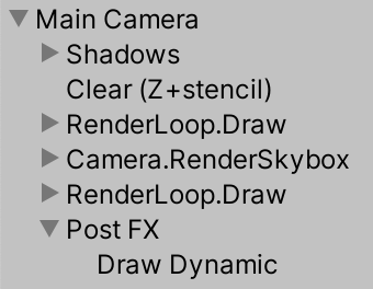
此时,结果看起来应该没有什么不同,但添加了一个额外的绘制步骤,从中间帧缓冲区复制到最终帧缓冲区。在帧调试器中,它被列为 Draw Dynamic。
强制清除
当绘制到中间帧缓冲区时,我们渲染到一个填充了任意数据的纹理。当帧调试器处于活动状态时,你可以看到这一点。Unity 确保帧调试器在每帧开始时获得一个清晰的帧缓冲区,但当我们渲染到自己的纹理时,我们会绕过这一点。通常会导致我们在前一帧的结果之上绘制,但这并不能保证。如果摄像机的 Clear Flags 设置为天空盒或纯色,这并不重要,因为我们保证完全覆盖之前的数据。但其他两个选项不起作用。为了防止出现随机结果,当栈处于活动状态时,始终清除深度,除非使用天空盒,否则也清除颜色。
1
2
3
4
5
6
7
8
CameraClearFlags flags = camera.clearFlags;
if (postFXStack.IsActive) {
    if (flags > CameraClearFlags.Color) {
        flags = CameraClearFlags.Color;
    }
    ...
}
buffer.ClearRenderTarget(...);
请注意,这使得在使用后处理 FX 栈时,无法让摄像机在不清除的情况下在另一个摄像机上渲染。有一些解决方法,但这超出了本教程的范围。
Gizmos
我们目前同时绘制所有 gizmos,但在后处理 FX 之前和之后应该渲染的 gizmos 是有区别的。因此,让我们将 DrawGizmos 方法分成两个。
1
2
3
4
5
6
7
8
9
10
11
12
13
14
15
16
17
18
partial void DrawGizmosBeforeFX ();
partial void DrawGizmosAfterFX ();
...

#if UNITY_EDITOR
...
partial void DrawGizmosBeforeFX () {
    if (Handles.ShouldRenderGizmos()) {
        context.DrawGizmos(camera, GizmoSubset.PreImageEffects);
        //context.DrawGizmos(camera, GizmoSubset.PostImageEffects);
    }
}

partial void DrawGizmosAfterFX () {
    if (Handles.ShouldRenderGizmos()) {
        context.DrawGizmos(camera, GizmoSubset.PostImageEffects);
    }
}
然后我们可以在 Render 中的正确时间绘制它们。
1
2
3
4
5
6
//DrawGizmos();
DrawGizmosBeforeFX();
if (postFXStack.IsActive) {
    postFXStack.Render(frameBufferId);
}
DrawGizmosAfterFX();
请注意,当栈处于活动状态时,当 gizmos 使用 3D 图标时,它们不再被对象遮挡。这是因为场景窗口依赖于原始帧缓冲区的深度数据,而我们不使用它。我们将在未来介绍深度与后处理 FX 的结合。
自定义绘制
我们目前使用的 Blit 方法绘制一个四边形网格(两个三角形),覆盖整个屏幕空间。但我们可以通过只绘制一个三角形来获得相同的结果,这样工作量会少一点。我们甚至不需要向 GPU 发送单三角形网格,我们可以程序化地生成它。
在我们 RP 的 Shaders 文件夹中创建一个 PostFXStackPasses.hlsl 文件。我们将把栈的所有 pass 放在那里。我们在其中定义的第一件事是 Varyings 结构,它只需要包含裁剪空间位置和屏幕空间 UV 坐标。
1
2
3
4
5
6
7
8
9
#ifndef CUSTOM_POST_FX_PASSES_INCLUDED
#define CUSTOM_POST_FX_PASSES_INCLUDED

struct Varyings {
    float4 positionCS : SV_POSITION;
    float2 screenUV : VAR_SCREEN_UV;
};

#endif
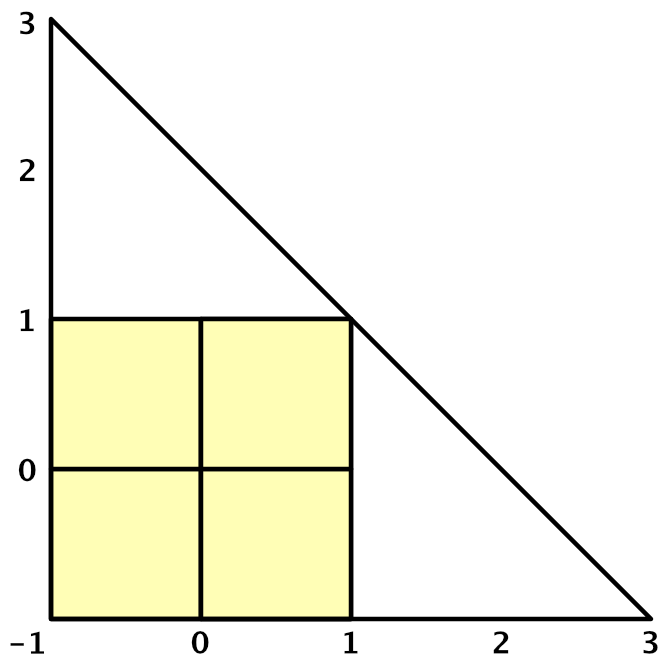
接下来,创建一个默认的顶点 pass,只有一个顶点标识符作为参数。它是一个无符号整数 uint,带有 SV_VertexID 语义。使用 ID 生成顶点位置和 UV 坐标。X 坐标为 -1、-1、3。Y 坐标为 -1、3、-1。为了使可见的 UV 坐标覆盖 0-1 范围,对 U 使用 0、0、2,对 V 使用 0、2、0。
1
2
3
4
5
6
7
8
9
10
11
12
13
Varyings DefaultPassVertex (uint vertexID : SV_VertexID) {
    Varyings output;
    output.positionCS = float4(
        vertexID <= 1 ? -1.0 : 3.0,
        vertexID == 1 ? 3.0 : -1.0,
        0.0, 1.0
    );
    output.screenUV = float2(
        vertexID <= 1 ? 0.0 : 2.0,
        vertexID == 1 ? 2.0 : 0.0
    );
    return output;
}
添加一个用于简单复制的片段 pass,最初返回 UV 坐标用于调试目的。
1
2
3
float4 CopyPassFragment (Varyings input) : SV_TARGET {
    return float4(input.screenUV, 0.0, 1.0);
}
在同一文件夹中创建一个配套的着色器文件。所有 pass 都将不使用剔除并忽略深度,因此我们可以将这些指令直接放在 SubShader 块中。我们还始终包含 Common 和 PostFXStackPasses 文件。现在它唯一的 pass 是用于复制的,使用我们创建的顶点和片段函数。我们还可以使用 Name 指令为其命名,这在同一着色器中组合多个 pass 时很方便,因为帧调试器将使用它作为 pass 标签,而不是数字。最后,将其菜单项放在 Hidden 文件夹下,这样在为材质选择着色器时就不会显示。
1
2
3
4
5
6
7
8
9
10
11
12
13
14
15
16
17
18
19
20
21
22
Shader "Hidden/Custom RP/Post FX Stack" {
    SubShader {
        Cull Off
        ZTest Always
        ZWrite Off

        HLSLINCLUDE
        #include "../ShaderLibrary/Common.hlsl"
        #include "PostFXStackPasses.hlsl"
        ENDHLSL

        Pass {
            Name "Copy"

            HLSLPROGRAM
            #pragma target 3.5
            #pragma vertex DefaultPassVertex
            #pragma fragment CopyPassFragment
            ENDHLSL
        }
    }
}
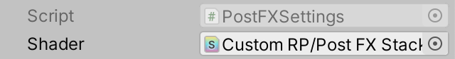
我们将通过其设置手动将着色器链接到我们的栈。
1
2
3
4
public class PostFXSettings : ScriptableObject {
    [SerializeField]
    Shader shader = default;
}
但我们在渲染时需要一个材质,所以添加一个公共属性,我们可以使用它直接从设置资产获取材质。我们将按需创建它,并设置为隐藏且不保存在项目中。此外,材质不能与资产一起序列化,因为它是按需创建的。
1
2
3
4
5
6
7
8
9
10
11
12
[System.NonSerialized]
Material material;

public Material Material {
    get {
        if (material == null && shader != null) {
            material = new Material(shader);
            material.hideFlags = HideFlags.HideAndDontSave;
        }
        return material;
    }
}
由于通过名称而不是数字来寻址 pass 更方便,因此在 PostFXStack 内部创建一个 Pass 枚举,最初只包含复制 pass。
1
2
3
enum Pass {
    Copy
}
现在我们可以定义自己的 Draw 方法。给它两个 RenderTargetIdentifier 参数来指示从哪里绘制到哪里,再加上一个 pass 参数。在其中,通过 _PostFXSource 纹理使源可用,像以前一样使用目标作为渲染目标,然后绘制三角形。我们通过在缓冲区上调用 DrawProcedural 来实现,参数包括一个未使用的矩阵、栈材质和 pass。之后还有两个参数。首先是我们正在绘制的形状类型,即 MeshTopology.Triangles。其次是我们想要多少个顶点,对于单个三角形来说是三个。
1
2
3
4
5
6
7
8
9
10
11
12
13
14
int fxSourceId = Shader.PropertyToID("_PostFXSource");
...
void Draw (
    RenderTargetIdentifier from, RenderTargetIdentifier to, Pass pass
) {
    buffer.SetGlobalTexture(fxSourceId, from);
    buffer.SetRenderTarget(
        to, RenderBufferLoadAction.DontCare, RenderBufferStoreAction.Store
    );
    buffer.DrawProcedural(
        Matrix4x4.identity, settings.Material, (int)pass,
        MeshTopology.Triangles, 3
    );
}
最后,用我们自己的方法替换 Blit 的调用。
1
2
//buffer.Blit(sourceId, BuiltinRenderTextureType.CameraTarget);
Draw(sourceId, BuiltinRenderTextureType.CameraTarget, Pass.Copy);
不总是应用 FX
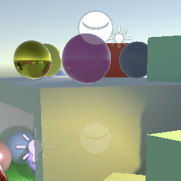
我们现在应该看到屏幕空间 UV 坐标出现在场景窗口中。在游戏窗口中也是如此。甚至在材质预览中,甚至在反射探头刷新后也是如此。
这个想法是后处理 FX 应用于适当的摄像机,仅此而已。我们可以通过在 PostFXStack.Setup 中检查我们是否有游戏或场景摄像机来强制执行此操作。如果没有,我们将设置设为 null,这将为该摄像机停用栈。
1
2
this.settings =
    camera.cameraType <= CameraType.SceneView ? settings : null;
除此之外,还可以通过场景窗口工具栏中的效果下拉菜单切换场景窗口中的后处理。可以同时打开多个场景窗口,它们可以分别启用或禁用后期效果。为了支持这一点,为 PostFXStack 创建一个编辑器部分类,其中包含一个 ApplySceneViewState 方法,该方法在构建中什么也不做。它的编辑器版本检查我们是否正在处理场景视图摄像机,如果是,则在当前绘制的场景视图的状态禁用了图像效果时禁用栈。
1
2
3
4
5
6
7
8
9
10
11
12
13
14
15
16
17
18
19
20
using UnityEditor;
using UnityEngine;

partial class PostFXStack {

    partial void ApplySceneViewState ();

#if UNITY_EDITOR

    partial void ApplySceneViewState () {
        if (
            camera.cameraType == CameraType.SceneView &&
            !SceneView.currentDrawingSceneView.sceneViewState.showImageEffects
        ) {
            settings = null;
        }
    }

#endif
}
在 Setup 的末尾调用此方法。
1
2
3
4
5
6
public partial class PostFXStack {
    ...
    public void Setup (...) {
        ...
        ApplySceneViewState();
    }
复制
我们通过使复制 pass 返回源颜色来完成栈。为此创建一个 GetSource 函数,它进行采样。我们将始终使用线性钳位采样器,因此我们可以显式声明它。
1
2
3
4
5
6
7
8
9
10
TEXTURE2D(_PostFXSource);
SAMPLER(sampler_linear_clamp);

float4 GetSource(float2 screenUV) {
    return SAMPLE_TEXTURE2D(_PostFXSource, sampler_linear_clamp, screenUV);
}

float4 CopyPassFragment (Varyings input) : SV_TARGET {
    return GetSource(input.screenUV);
}
因为我们的缓冲区永远不会有 mip 贴图,我们可以通过用 SAMPLE_TEXTURE2D_LOD 替换 SAMPLE_TEXTURE2D 来绕过自动 mip 贴图选择,添加一个额外的参数来强制选择 mip 贴图级别零。
1
return SAMPLE_TEXTURE2D_LOD(_PostFXSource, sampler_linear_clamp, screenUV, 0);
我们最终得到了原始图像,但在某些情况下它是上下颠倒的,通常在场景窗口中。这取决于图形 API 以及源和目标的类型。发生这种情况是因为某些图形 API 让纹理 V 坐标从顶部开始,而其他 API 让它从底部开始。Unity 通常会隐藏这一点,但在涉及渲染纹理的所有情况下都无法做到。幸运的是,Unity 通过 _ProjectionParams 向量的 X 分量指示是否需要手动翻转,我们应该在 UnityInput 中定义它。
1
float4 _ProjectionParams;
如果值为负,我们必须在 DefaultPassVertex 中翻转 V 坐标。
1
2
3
4
5
6
7
Varyings DefaultPassVertex (uint vertexID : SV_VertexID) {
    ...
    if (_ProjectionParams.x < 0.0) {
        output.screenUV.y = 1.0 - output.screenUV.y;
    }
    return output;
}
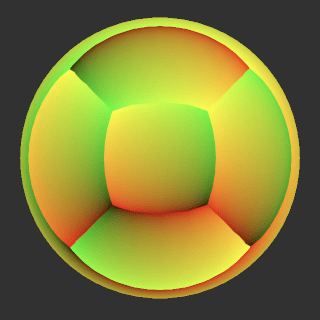
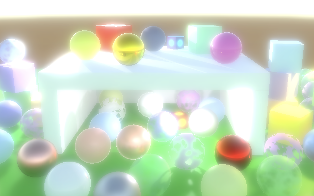
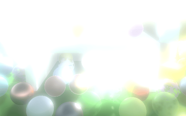
泛光效果
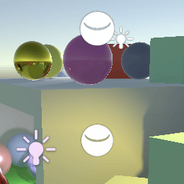
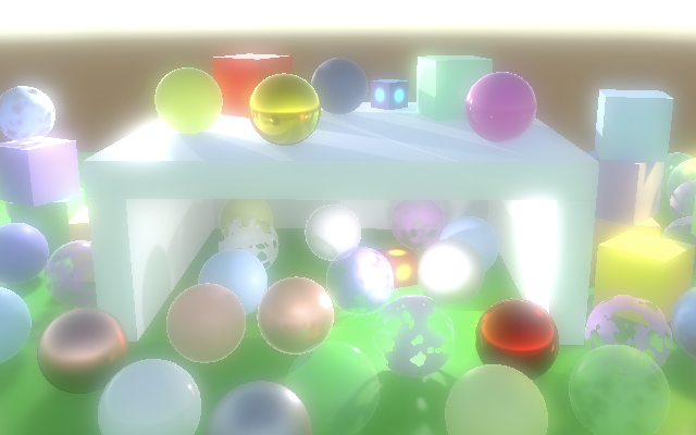
泛光后处理效果用于使物体发光。这在物理学中有基础,但经典的泛光效果是艺术性的而非现实的。非真实的泛光非常明显,因此是演示我们的后处理 FX 栈工作的一个很好的效果。我们将在下一个教程中介绍更真实的泛光,届时我们将介绍 HDR 渲染。现在我们的目标是 LDR 泛光发光效果。
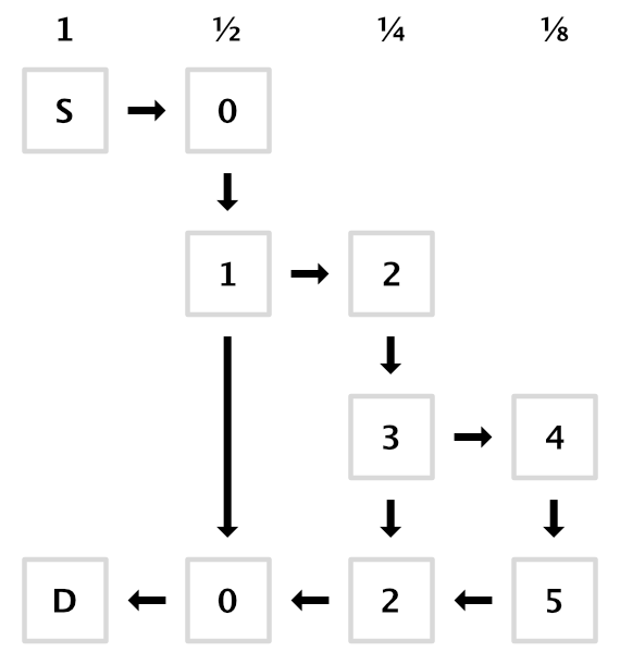
泛光金字塔
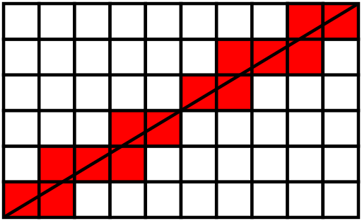
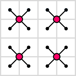
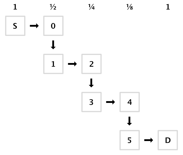
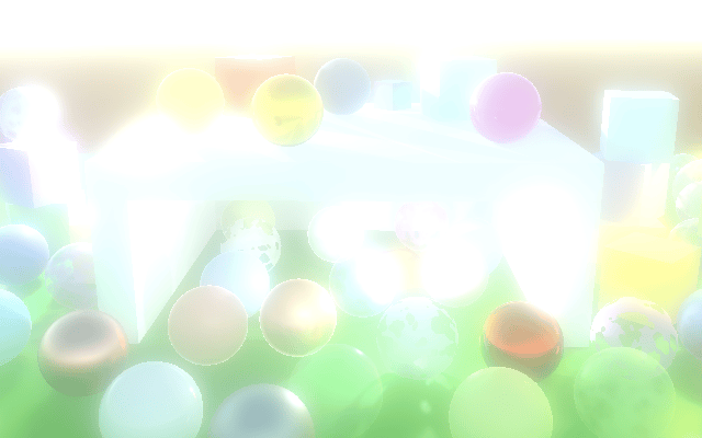
泛光代表颜色的散射,可以通过模糊图像来完成。明亮的像素会渗入相邻较暗的像素,从而看起来发光。模糊纹理的最简单和最快的方法是将其复制到宽度和高度减半的另一个纹理。复制 pass 的每个样本最终会在四个源像素之间采样。使用双线性过滤,这会平均 2×2 像素块。
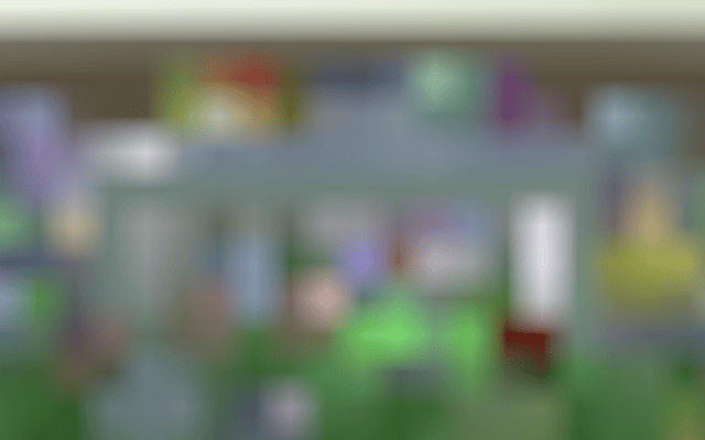
仅执行一次只会稍微模糊。因此,我们重复此过程,逐步降采样直到所需的级别,有效地构建纹理金字塔。
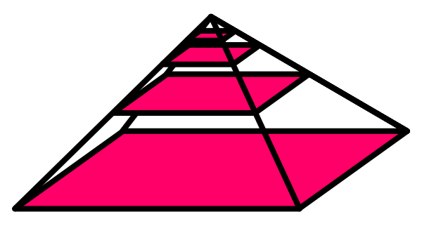
我们需要在栈中跟踪纹理,但有多少取决于金字塔中有多少级别,这取决于源图像大小。让我们在 PostFXStack 中定义最多十六个级别,这足以将 65,536×65,526 纹理一直缩放到单个像素。
1
const int maxBloomPyramidLevels = 16;
为了跟踪金字塔中的纹理,我们需要纹理标识符。我们将使用属性名称 _BloomPyramid0、_BloomPyramid1 等。但让我们不要显式编写所有这十六个名称。相反,我们将在构造函数方法中获取标识符,只跟踪第一个。这是因为 Shader.PropertyToID 只是按请求新属性名称的顺序依次分配标识符。我们只需要确保一次请求所有标识符,因为每个应用程序会话的数字是固定的,无论是在编辑器中还是在构建中。
1
2
3
4
5
6
7
8
int bloomPyramidId;
...
public PostFXStack () {
    bloomPyramidId = Shader.PropertyToID("_BloomPyramid0");
    for (int i = 1; i < maxBloomPyramidLevels; i++) {
        Shader.PropertyToID("_BloomPyramid" + i);
    }
}
现在创建一个 DoBloom 方法,为给定的源标识符应用泛光效果。首先将摄像机的像素宽度和高度减半,并选择默认的渲染纹理格式。最初,我们将从源复制到金字塔中的第一个纹理。跟踪这些标识符。
1
2
3
4
5
6
7
void DoBloom (int sourceId) {
    buffer.BeginSample("Bloom");
    int width = camera.pixelWidth / 2, height = camera.pixelHeight / 2;
    RenderTextureFormat format = RenderTextureFormat.Default;
    int fromId = sourceId, toId = bloomPyramidId;
    buffer.EndSample("Bloom");
}
然后循环遍历所有金字塔级别。每次迭代,首先检查级别是否会退化。如果是,我们就在那一点停止。如果不是,获取一个新的渲染纹理,复制到它,将其设为新源,递增目标,并再次将尺寸减半。在循环外声明循环迭代器变量,因为我们稍后需要它。
1
2
3
4
5
6
7
8
9
10
11
12
13
14
15
int fromId = sourceId, toId = bloomPyramidId;
int i;
for (i = 0; i < maxBloomPyramidLevels; i++) {
    if (height < 1 || width < 1) {
        break;
    }
    buffer.GetTemporaryRT(
        toId, width, height, 0, FilterMode.Bilinear, format
    );
    Draw(fromId, toId, Pass.Copy);
    fromId = toId;
    toId += 1;
    width /= 2;
    height /= 2;
}
金字塔完成后,将最终结果复制到摄像机目标。然后递减迭代器并向后循环,释放我们声明的所有纹理。
1
2
3
4
5
6
7
8
for (i = 0; i < maxBloomPyramidLevels; i++) { ... }

Draw(fromId, BuiltinRenderTextureType.CameraTarget, Pass.Copy);

for (i -= 1; i >= 0; i--) {
    buffer.ReleaseTemporaryRT(bloomPyramidId + i);
}
buffer.EndSample("Bloom");
现在我们可以在 Render 中用泛光效果替换简单的复制。
1
2
3
4
5
6
public void Render (int sourceId) {
    //Draw(sourceId, BuiltinRenderTextureType.CameraTarget, Pass.Copy);
    DoBloom(sourceId);
    context.ExecuteCommandBuffer(buffer);
    buffer.Clear();
}
可配置的泛光
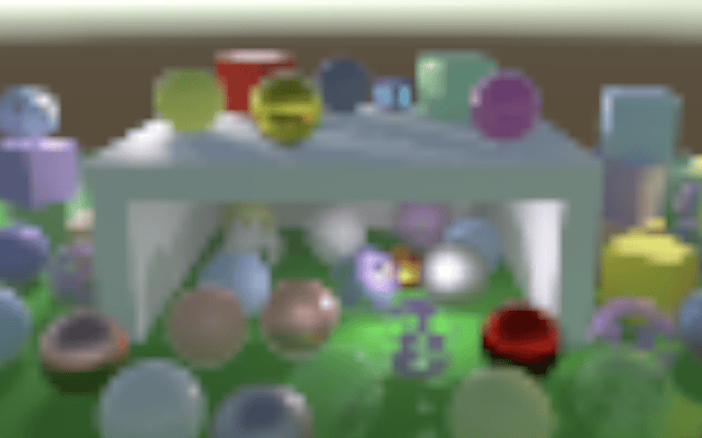
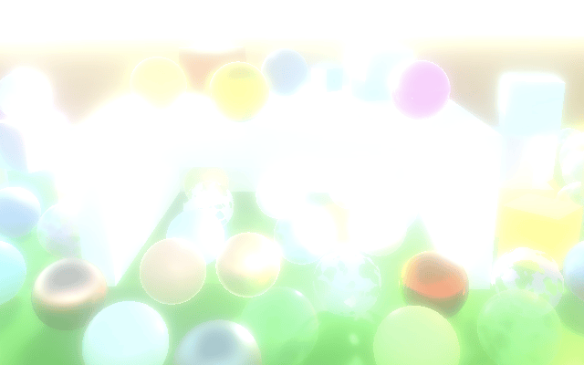
我们现在模糊得太多了,以至于最终结果几乎是均匀的。你可以通过帧调试器检查中间步骤。这些步骤作为端点看起来更有用,所以让我们可以提前停止。
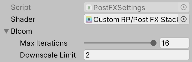
我们可以通过两种方式做到这一点。首先,我们可以限制模糊迭代的数量。其次,我们可以将降采样限制设置为更高的值。让我们同时支持这两者,通过在 PostFXSettings 中添加一个 BloomSettings 配置结构,并为它们提供选项。通过 getter 属性使其公开可用。
1
2
3
4
5
6
7
8
9
10
11
12
13
[System.Serializable]
public struct BloomSettings {
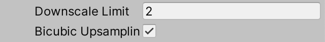
[Range(0f, 16f)]
public int maxIterations;
[Min(1f)]
public int downscaleLimit;
}
[SerializeField]
BloomSettings bloom = default;
public BloomSettings Bloom => bloom;
让 PostFXStack.DoBloom 使用这些设置来限制自己。
1
2
3
4
5
6
7
8
9
10
11
12
13
14
PostFXSettings.BloomSettings bloom = settings.Bloom;
int width = camera.pixelWidth / 2, height = camera.pixelHeight / 2;
RenderTextureFormat format = RenderTextureFormat.Default;
int fromId = sourceId, toId = bloomPyramidId;
int i;
for (i = 0; i < bloom.maxIterations; i++) {
    if (height < bloom.downscaleLimit || width < bloom.downscaleLimit) {
        break;
    }
    buffer.GetTemporaryRT(
        toId, width, height, 0, FilterMode.Bilinear, format
    );
    ...
}
高斯滤波
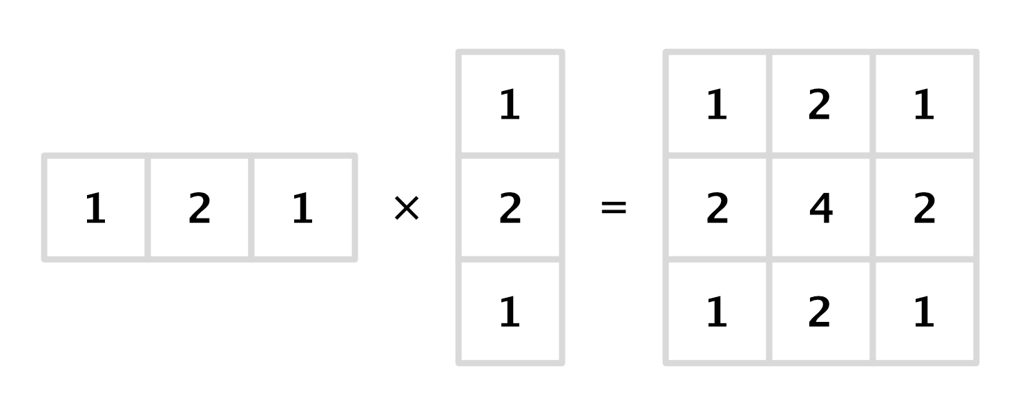
使用小的 2×2 滤波器降采样会产生非常块状的结果。可以通过使用更大的滤波核(例如近似 9×9 高斯滤波器)来大大改善效果。如果我们将此与双线性降采样相结合,我们将其加倍为有效的 18×18。这就是通用 RP 和 HDRP 用于其泛光的方法。
尽管此操作混合了 81 个样本,但它是可分离的,这意味着它可以分为水平和垂直 pass,每个 pass 混合九个样本的单行或单列。因此,我们只需要采样 18 次,但每次迭代需要两次绘制。
让我们从水平 pass 开始。在 PostFXStackPasses 中为其创建一个新的 BloomHorizontalPassFragment 函数。它累积以当前 UV 坐标为中心的九个样本的行。我们同时进行降采样,因此每个偏移步长是源纹素宽度的两倍。从左边开始的样本权重为 0.01621622、0.05405405、0.12162162、0.19459459,然后中心为 0.22702703,另一侧则相反。
1
2
3
4
5
6
7
8
9
10
11
12
13
14
15
16
17
18
19
20
21
float4 _PostFXSource_TexelSize;

float4 GetSourceTexelSize () {
    return _PostFXSource_TexelSize;
}
...
float4 BloomHorizontalPassFragment (Varyings input) : SV_TARGET {
    float3 color = 0.0;
    float offsets[] = {
        -4.0, -3.0, -2.0, -1.0, 0.0, 1.0, 2.0, 3.0, 4.0
    };
    float weights[] = {
        0.01621622, 0.05405405, 0.12162162, 0.19459459, 0.22702703,
        0.19459459, 0.12162162, 0.05405405, 0.01621622
    };
    for (int i = 0; i < 9; i++) {
        float offset = offsets[i] * 2.0 * GetSourceTexelSize().x;
        color += GetSource(input.screenUV + float2(offset, 0.0)).rgb * weights[i];
    }
    return float4(color, 1.0);
}
还要在 PostFXStack 着色器中为其添加一个 pass。我将其放在复制 pass 上方,以按字母顺序保持它们。
1
2
3
4
5
6
7
8
9
Pass {
    Name "Bloom Horizontal"

    HLSLPROGRAM
    #pragma target 3.5
    #pragma vertex DefaultPassVertex
    #pragma fragment BloomHorizontalPassFragment
    ENDHLSL
}
也将其添加到 PostFXStack.Pass 枚举中,同样按相同的顺序。
1
2
3
4
enum Pass {
    BloomHorizontal,
    Copy
}
现在我们可以在 DoBloom 中降采样时使用 bloom-horizontal pass。
1
Draw(fromId, toId, Pass.BloomHorizontal);
此时,结果明显水平拉伸,但看起来很有希望。我们可以通过复制 BloomHorizontalPassFragment、重命名并从行切换到列来创建垂直 pass。我们在第一个 pass 中进行了降采样,但这次我们保持相同的大小以完成高斯滤波器,因此纹素大小偏移不应加倍。
1
2
3
4
5
6
7
8
9
10
11
12
13
14
15
float4 BloomVerticalPassFragment (Varyings input) : SV_TARGET {
    float3 color = 0.0;
    float offsets[] = {
        -4.0, -3.0, -2.0, -1.0, 0.0, 1.0, 2.0, 3.0, 4.0
    };
    float weights[] = {
        0.01621622, 0.05405405, 0.12162162, 0.19459459, 0.22702703,
        0.19459459, 0.12162162, 0.05405405, 0.01621622
    };
    for (int i = 0; i < 9; i++) {
        float offset = offsets[i] * GetSourceTexelSize().y;
        color += GetSource(input.screenUV + float2(0.0, offset)).rgb * weights[i];
    }
    return float4(color, 1.0);
}
也为其添加一个 pass 和枚举条目。从现在开始,我不会再显示这些步骤。
我们现在需要在每个金字塔级别中间添加一个额外的步骤,为此我们还必须保留纹理标识符。我们可以通过简单地将 PostFXStack 构造函数中的循环限制加倍来做到这一点。由于我们还没有引入其他着色器属性名称,因此标识符将全部按顺序排列,否则需要重新启动 Unity。
1
2
3
4
5
6
public PostFXStack () {
    bloomPyramidId = Shader.PropertyToID("_BloomPyramid0");
    for (int i = 1; i < maxBloomPyramidLevels * 2; i++) {
        Shader.PropertyToID("_BloomPyramid" + i);
    }
}
在 DoBloom 中,目标标识符现在必须从高一位开始,并在每个降采样步骤后增加二。然后可以将中间纹理放在中间。水平绘制到中间,然后是垂直绘制到目标。我们还必须释放额外的纹理,从最后一个金字塔源向后工作是最简单的。
1
2
3
4
5
6
7
8
9
10
11
12
13
14
15
16
17
18
19
20
21
22
23
24
25
26
27
28
void DoBloom (int sourceId) {
    ...
    int fromId = sourceId, toId = bloomPyramidId + 1;
    for (i = 0; i < bloom.maxIterations; i++) {
        ...
        int midId = toId - 1;
        buffer.GetTemporaryRT(
            midId, width, height, 0, FilterMode.Bilinear, format
        );
        buffer.GetTemporaryRT(
            toId, width, height, 0, FilterMode.Bilinear, format
        );
        Draw(fromId, midId, Pass.BloomHorizontal);
        Draw(midId, toId, Pass.BloomVertical);
        fromId = toId;
        toId += 2;
        ...
    }

    Draw(fromId, BuiltinRenderTextureType.CameraTarget, Pass.Copy);

    for (i -= 1; i >= 0; i--) {
        buffer.ReleaseTemporaryRT(fromId);
        buffer.ReleaseTemporaryRT(fromId - 1);
        fromId -= 2;
    }
    buffer.EndSample("Bloom");
}

我们的降采样滤波器现在已经完成,看起来比简单的双线性滤波好得多,代价是更多的纹理样本。幸运的是,我们可以通过使用双线性滤波在适当偏移处的高斯采样点之间采样来稍微减少样本量。这将九个样本减少到只有五个。我们可以在 BloomVerticalPassFragment 中使用此技巧。偏移在两个方向上变为 3.23076923 和 1.38461538,权重为 0.07027027 和 0.31621622。
1
2
3
4
5
6
7
8
9
10
float offsets[] = {
    -3.23076923, -1.38461538, 0.0, 1.38461538, 3.23076923
};
float weights[] = {
    0.07027027, 0.31621622, 0.22702703, 0.31621622, 0.07027027
};
for (int i = 0; i < 5; i++) {
    float offset = offsets[i] * GetSourceTexelSize().y;
    color += GetSource(input.screenUV + float2(0.0, offset)).rgb * weights[i];
}
我们不能在 BloomHorizontalPassFragment 中这样做,因为我们已经在该 pass 中使用双线性滤波进行降采样。它的九个样本中的每一个都平均 2×2 源像素。
叠加模糊
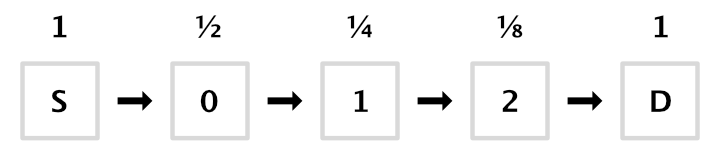
使用泛光金字塔的顶部作为最终图像会产生均匀的混合,看起来不像任何东西在发光。我们可以通过逐步向下上采样金字塔,在单个图像中累积所有级别来获得所需的结果。
我们可以使用叠加混合来组合两个图像,但让我们对所有 pass 使用相同的混合模式,而是添加第二个源纹理。在 PostFXStack 中为其声明一个标识符。
1
2
3
int
    fxSourceId = Shader.PropertyToID("_PostFXSource"),
    fxSource2Id = Shader.PropertyToID("_PostFXSource2");
然后在 DoBloom 中完成金字塔后不再直接执行最终绘制。相反,释放用于最后一次迭代的水平绘制的纹理,并将目标设置为用于低一级的水平绘制的纹理。
1
2
3
//Draw(fromId, BuiltinRenderTextureType.CameraTarget, Pass.Copy);
buffer.ReleaseTemporaryRT(fromId - 1);
toId -= 5;
当我们向后循环时,我们每次迭代再次绘制,方向相反,每个级别的结果作为第二个源。这仅适用于第一级,因此我们必须提前一步停止。之后,使用原始图像作为辅助源绘制到最终目标。
1
2
3
4
5
6
7
8
9
10
11
12
13
for (i -= 1; i > 0; i--) {
    buffer.SetGlobalTexture(fxSource2Id, toId + 1);
    Draw(fromId, toId, Pass.Copy);
    buffer.ReleaseTemporaryRT(fromId);
    buffer.ReleaseTemporaryRT(toId + 1);
    fromId = toId;
    toId -= 2;
}

buffer.SetGlobalTexture(fxSource2Id, sourceId);
Draw(fromId, BuiltinRenderTextureType.CameraTarget, Pass.Copy);
buffer.ReleaseTemporaryRT(fromId);
buffer.EndSample("Bloom");
要使其工作,我们需要使辅助源可用于着色器 pass。
1
2
3
4
5
6
7
TEXTURE2D(_PostFXSource);
TEXTURE2D(_PostFXSource2);
SAMPLER(sampler_linear_clamp);
...
float4 GetSource2(float2 screenUV) {
    return SAMPLE_TEXTURE2D_LOD(_PostFXSource2, sampler_linear_clamp, screenUV, 0);
}
并引入一个新的 bloom-combine pass,它对两个纹理进行采样并相加。和以前一样,我只展示片段程序,不展示新的着色器 pass 或新的枚举条目。
1
2
3
4
5
float4 BloomCombinePassFragment (Varyings input) : SV_TARGET {
    float3 lowRes = GetSource(input.screenUV).rgb;
    float3 highRes = GetSource2(input.screenUV).rgb;
    return float4(lowRes + highRes, 1.0);
}
在上采样时使用新 pass。
1
2
3
4
5
6
7
8
9
10
11
for (i -= 1; i > 0; i--) {
    buffer.SetGlobalTexture(fxSource2Id, toId + 1);
    Draw(fromId, toId, Pass.BloomCombine);
    ...
}

buffer.SetGlobalTexture(fxSource2Id, sourceId);
Draw(
    bloomPyramidId, BuiltinRenderTextureType.CameraTarget,
    Pass.BloomCombine
);
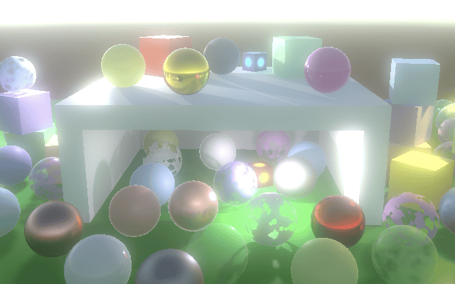
我们终于有了一个看起来一切都在发光的效果。但我们的新方法只有在至少有两次迭代时才有效。如果我们最终只执行一次迭代,那么我们应该跳过整个上采样阶段,只需释放用于第一个水平 pass 的纹理。
1
2
3
4
5
6
7
8
9
10
if (i > 1) {
    buffer.ReleaseTemporaryRT(fromId - 1);
    toId -= 5;
    for (i -= 1; i > 0; i--) {
        ...
    }
}
else {
    buffer.ReleaseTemporaryRT(bloomPyramidId);
}
如果我们最终完全跳过泛光,我们必须中止并执行复制。
1
2
3
4
5
6
7
8
9
int width = camera.pixelWidth / 2, height = camera.pixelHeight / 2;
if (
    bloom.maxIterations == 0 ||
    height < bloom.downscaleLimit || width < bloom.downscaleLimit
) {
    Draw(sourceId, BuiltinRenderTextureType.CameraTarget, Pass.Copy);
    buffer.EndSample("Bloom");
    return;
}
双三次上采样
尽管高斯滤波器产生平滑的结果,但我们在上采样时仍然执行双线性滤波,这可能会使发光呈现块状外观。这在原始图像对比度高的地方最为明显,尤其是在运动时。
我们可以通过切换到双三次滤波来消除这些伪影。对此没有硬件支持,但我们可以使用 Core RP Library 的 Filtering 包含文件中定义的 SampleTexture2DBicubic 函数。使用它创建我们自己的 GetSourceBicubic 函数,传递纹理和采样器状态、UV 坐标,以及交换了大小对的纹素大小向量。除此之外,它有一个最大纹理坐标的参数,简单地为 1,然后是另一个未使用的参数,可以只是零。
1
2
3
4
5
6
7
8
#include "Packages/com.unity.render-pipelines.core/ShaderLibrary/Filtering.hlsl"
...
float4 GetSourceBicubic (float2 screenUV) {
    return SampleTexture2DBicubic(
        TEXTURE2D_ARGS(_PostFXSource, sampler_linear_clamp), screenUV,
        _PostFXSource_TexelSize.zwxy, 1.0, 0.0
    );
}
在 bloom-combine pass 中使用新函数,以便我们使用双三次滤波进行上采样。
1
2
3
4
5
float4 BloomCombinePassFragment (Varyings input) : SV_TARGET {
    float3 lowRes = GetSourceBicubic(input.screenUV).rgb;
    float3 highRes = GetSource2(input.screenUV).rgb;
    return float4(lowRes + highRes, 1.0);
}

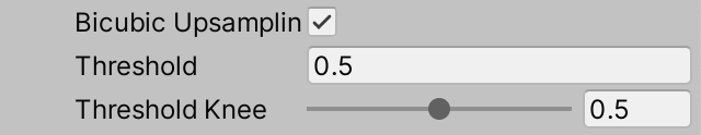
双三次采样产生更好的结果,但需要四个加权纹理样本而不是单个样本。因此,让我们通过着色器布尔值使其可选,以防不需要。这对应于通用 RP 和 HDRP 的高质量泛光切换。
1
2
3
4
5
6
7
8
9
10
11
12
13
bool _BloomBicubicUpsampling;

float4 BloomCombinePassFragment (Varyings input) : SV_TARGET {
    float3 lowRes;
    if (_BloomBicubicUpsampling) {
        lowRes = GetSourceBicubic(input.screenUV).rgb;
    }
    else {
        lowRes = GetSource(input.screenUV).rgb;
    }
    float3 highRes = GetSource2(input.screenUV).rgb;
    return float4(lowRes + highRes, 1.0);
}
在 PostFXSettings.BloomSettings 中为其添加一个切换选项。
1
public bool bicubicUpsampling;
并在开始上采样之前,在 PostFXStack.DoBloom 中将其传递给 GPU。
1
2
3
4
5
6
7
8
9
10
11
12
13
int
    bloomBucibicUpsamplingId = Shader.PropertyToID("_BloomBicubicUpsampling"),
    fxSourceId = Shader.PropertyToID("_PostFXSource"),
    fxSource2Id = Shader.PropertyToID("_PostFXSource2");
...
void DoBloom (int sourceId) {
    ...
    buffer.SetGlobalFloat(
        bloomBucibicUpsamplingId, bloom.bicubicUpsampling ? 1f : 0f
    );
    if (i > 1) { ... }
    ...
}
半分辨率
由于所有纹理采样和绘制,泛光可能需要很长时间来生成。减少成本的一个简单方法是以半分辨率生成它。由于效果是柔和的,我们可以这样做。这将改变效果的外观,因为我们实际上跳过了第一次迭代。
首先,在决定跳过泛光时,我们应该向前看一步。实际上,对于初始检查,降采样限制加倍。
1
2
3
4
5
6
7
8
if (
    bloom.maxIterations == 0 ||
    height < bloom.downscaleLimit * 2 || width < bloom.downscaleLimit * 2
) {
    Draw(sourceId, BuiltinRenderTextureType.CameraTarget, Pass.Copy);
    buffer.EndSample("Bloom");
    return;
}
其次,我们需要为半尺寸图像声明一个纹理,我们将其用作新的起点。它不是泛光金字塔的一部分,因此我们将为其声明一个新的标识符。我们将其用于预过滤步骤,因此适当地命名它。
1
2
3
4
int
    bloomBucibicUpsamplingId = Shader.PropertyToID("_BloomBicubicUpsampling"),
    bloomPrefilterId = Shader.PropertyToID("_BloomPrefilter"),
    ...
回到 DoBloom,将源复制到预过滤纹理,并将其用于金字塔的起点,同时再次将宽度和高度减半。我们在向上遍历金字塔后不再需要预过滤纹理,因此可以在那时释放它。
1
2
3
4
5
6
7
8
9
10
11
12
13
14
15
RenderTextureFormat format = RenderTextureFormat.Default;
buffer.GetTemporaryRT(
    bloomPrefilterId, width, height, 0, FilterMode.Bilinear, format
);
Draw(sourceId, bloomPrefilterId, Pass.Copy);
width /= 2;
height /= 2;

int fromId = bloomPrefilterId, toId = bloomPyramidId + 1;
int i;
for (i = 0; i < bloom.maxIterations; i++) {
    ...
}

buffer.ReleaseTemporaryRT(bloomPrefilterId);
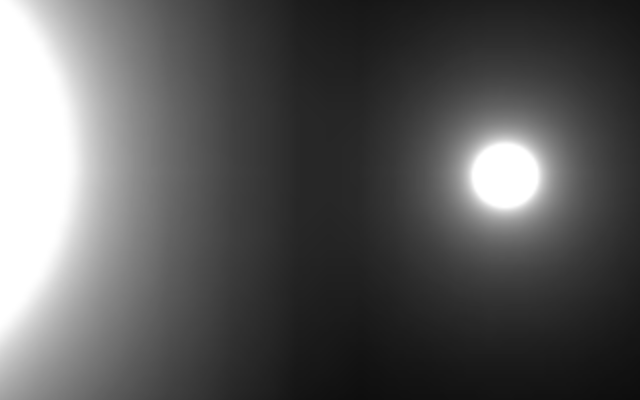
阈值
泛光通常被艺术性地用来使只有某些东西发光,但我们的效果目前适用于一切,无论它有多亮。尽管在物理上没有意义,但我们可以通过引入亮度阈值来限制对效果的贡献。
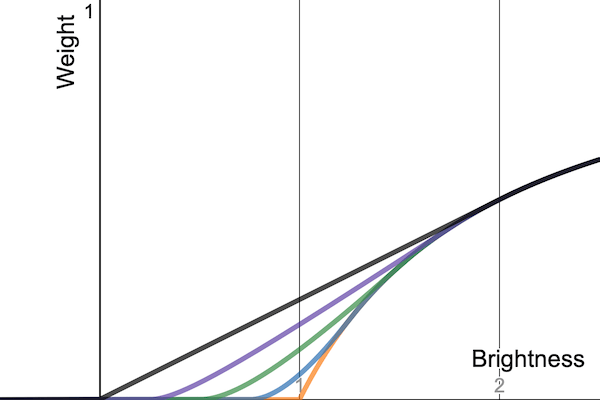
我们不能突然从效果中消除颜色,因为这会在预期逐渐过渡的地方引入尖锐的边界。相反,我们将颜色乘以权重 $w = \frac{\max(0, b - t)}{\max(b, 0.00001)}$,其中 $b$ 是其亮度,$t$ 是配置的阈值。我们将使用颜色 RGB 通道的最大值作为 $b$。当阈值为零时,结果始终为 1,这使颜色保持不变。随着阈值的增加,权重曲线将向下弯曲,因此在 $b \leq t$ 处变为零。由于曲线的形状,它被称为拐点曲线。
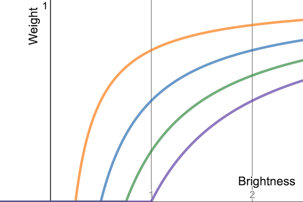
这条曲线以一个角度达到零,这意味着尽管过渡比钳位更平滑,但仍然有一个突然的切断点。这就是为什么它也被称为硬拐点。我们可以通过将权重更改为 $w = \frac{\max(s, b - t)}{\max(b, 0.00001)}$ 来控制拐点的形状,其中 $s = \frac{\min(\max(0, b - t + tk), 2tk)^2}{4tk + 0.00001}$,$k$ 为 0-1 的拐点滑块。
让我们将阈值和拐点滑块都添加到 PostFXSettings.BloomSettings 中。我们将把配置的阈值视为 gamma 值,因为这在视觉上更直观,因此在将其发送到 GPU 时,我们必须将其转换为线性空间。我们使其开放式,即使大于零的阈值此时将消除所有颜色,因为我们仅限于 LDR。
1
2
3
4
5
[Min(0f)]
public float threshold;

[Range(0f, 1f)]
public float thresholdKnee;
我们将通过一个名为 _BloomThreshold 的向量将阈值值发送到 GPU。在 PostFXStack 中为其声明一个标识符。
1
2
bloomPrefilterId = Shader.PropertyToID("_BloomPrefilter"),
bloomThresholdId = Shader.PropertyToID("_BloomThreshold"),
我们可以计算权重函数的常量部分,并将它们放在向量的四个分量中,以保持着色器更简单:$[t, -t + tk, 2tk, \frac{1}{4tk + 0.00001}]$。
我们将在一个新的预过滤 pass 中使用它,它替换 DoBloom 中的初始复制 pass,从而在我们将图像尺寸减半时将阈值应用于 2×2 像素的平均值。
1
2
3
4
5
6
7
8
9
10
11
12
13
Vector4 threshold;
threshold.x = Mathf.GammaToLinearSpace(bloom.threshold);
threshold.y = threshold.x * bloom.thresholdKnee;
threshold.z = 2f * threshold.y;
threshold.w = 0.25f / (threshold.y + 0.00001f);
threshold.y -= threshold.x;
buffer.SetGlobalVector(bloomThresholdId, threshold);

RenderTextureFormat format = RenderTextureFormat.Default;
buffer.GetTemporaryRT(
    bloomPrefilterId, width, height, 0, FilterMode.Bilinear, format
);
Draw(sourceId, bloomPrefilterId, Pass.BloomPrefilter);
将阈值向量和一个将其应用于颜色的函数添加到 PostFXShaderPasses,然后是使用它的新 pass 函数。
1
2
3
4
5
6
7
8
9
10
11
12
13
14
15
16
17
float4 _BloomThreshold;

float3 ApplyBloomThreshold (float3 color) {
    float brightness = Max3(color.r, color.g, color.b);
    float soft = brightness + _BloomThreshold.y;
    soft = clamp(soft, 0.0, _BloomThreshold.z);
    soft = soft * soft * _BloomThreshold.w;
    float contribution = max(soft, brightness - _BloomThreshold.x);
    contribution /= max(brightness, 0.00001);
    return color * contribution;
}

float4 BloomPrefilterPassFragment (Varyings input) : SV_TARGET {
    float3 color = ApplyBloomThreshold(GetSource(input.screenUV).rgb);
    return float4(color, 1.0);
}
强度
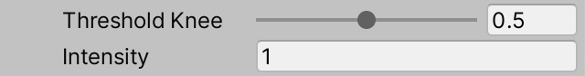
我们通过添加一个强度滑块来控制泛光的整体强度来结束本教程。我们不会给它设置限制,因此如果需要,可以使整个图像过曝。
1
2
[Min(0f)]
public float intensity;
如果强度设置为零,我们可以跳过泛光,因此在 DoBloom 的开头检查这一点。
1
2
3
4
5
6
7
8
if (
    bloom.maxIterations == 0 || bloom.intensity <= 0f ||
    height < bloom.downscaleLimit * 2 || width < bloom.downscaleLimit * 2
) {
    Draw(sourceId, BuiltinRenderTextureType.CameraTarget, Pass.Copy);
    buffer.EndSample("Bloom");
    return;
}
否则,使用 _BloomIntensity 的新标识符将强度传递给 GPU。我们将使用它在组合 pass 期间对低分辨率图像进行加权,因此我们不需要创建额外的 pass。对于除最终绘制到摄像机目标之外的所有绘制,将其设置为 1。
1
2
3
4
5
6
7
8
9
10
11
buffer.SetGlobalFloat(bloomIntensityId, 1f);
if (i > 1) {
    ...
}
else {
    buffer.ReleaseTemporaryRT(bloomPyramidId);
}

buffer.SetGlobalFloat(bloomIntensityId, bloom.intensity);
buffer.SetGlobalTexture(fxSource2Id, sourceId);
Draw(fromId, BuiltinRenderTextureType.CameraTarget, Pass.BloomCombine);
现在我们只需要在 BloomCombinePassFragment 中将低分辨率颜色乘以强度。
1
2
3
4
5
6
7
bool _BloomBicubicUpsampling;
float _BloomIntensity;

float4 BloomCombinePassFragment (Varyings input) : SV_TARGET {
    ...
    return float4(lowRes * _BloomIntensity + highRes, 1.0);
}
下一个教程是HDR。