Unity Deferred Lights-延迟光照(翻译十五)
本篇摘要:
- 自定义灯光渲染
- 解码LDR颜色
- 增加独立Pass渲染光
- 支持方向光、点光源、聚光灯
- 手动采样阴影纹理
光照Light Shader
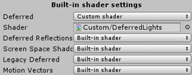
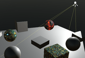
在G-Buffers填充完毕后,然后渲染光。本篇先介绍Unity是如何渲染光,以及实现自己的渲染光的Shader。在Edit / Project Settings / Graphics 去掉默认的Shader。
Using a Custom Shader
每个deferred光都是在一个独立的Pass修改屏幕图像(后处理Image)完成渲染。创建一个Shader然后指定到Built-In shader settings
第二个PassA Second Pass
修改之后,编辑器大量报错.
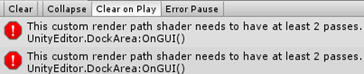
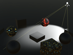
先简单复制第一个Pass解决错误,结果是屏幕内除了天空盒外所有物体被渲染成黑色了。这是因为使用了stencil-buffer。
报错的原因:为什么需要第二个Pass?
- 当HDR禁用时,光照数据会被使用对数编码计算,然后在(第二个)最终的pass解码该数据。所以必须要增加Pass。当禁用HDR时就能调用第二个Pass,但此时天空也变黑了。
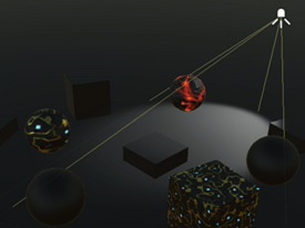
Avoiding the Sky
当在LDR(HDR禁用)模式,天空变黑了。这是因为转换过程中没有正确使用stencil-buffer模板掩码。在第二个Pass中配置:应该只渲染不属于背景的片段,可通过_StencilNonBackground提供适当的模板值。
1
2
3
4
5
6
7
8
9
10
Pass
{
    Stencil
    {
        Ref[_StencilNonBackground]
        ReadMask[_StencilNonBackground]
        CompBack Equal
        CompFront Equal
    }
}
颜色转换Converting Colors
在第二个Pass的light-buffer转换光照数据,方法就似Fog shader:用输入源的Image UV坐标采样buffer来绘制一个覆盖全屏的quad
1
2
3
4
5
6
7
8
9
10
11
12
13
14
struct VertexData {
    float4 vertex : POSITION;
    float2 uv : TEXCOORD0;
};
struct Interpolators {
    float4 pos : SV_POSITION;
    float2 uv : TEXCOORD0;
};
Interpolators VertexProgram (VertexData v) {
    Interpolators i;
    i.pos = UnityObjectToClipPos(v.vertex);
    i.uv = v.uv;
    return i;
}
该light buffer通过名为_LightBuffer变量提供给Shader
1
2
3
4
5
sampler2D _LightBuffer;
//...
float4 FragmentProgram (Interpolators i) : SV_Target {
    return tex2D(_LightBuffer, i.uv);
}
LDR颜色使用指数编码: $2^{-C}$,使用对数解码 $-log2^C$
1
return -log2(tex2D(_LightBuffer, i.uv));
Directional Lights
新增一个cginc文件,引入第一个pass。要把渲染的光照增加到图像上,必须确保不能擦除已渲染的图像,因此改变混合模式要完全合并源颜色和目标颜色。
1
Blend One One
也需要所有可能的光照配置shader variants变体,该编译指令:multi_compile_lightpass会创建所有包含的变体。然后再增加一个HDR_ON的指令。
1
2
#pragma multi_compile_lightpass
#pragma multi_compile _ UNITY_HDR_ON
G-Buffer UV Coordinates
需要用UV坐标从G-buffers采样,不幸的是,该light pass通道unity不支持提供该坐标。解决办法:从clip-space传递过来,使用ComputeScreenPos函数计算,返回一个float4的齐次坐标。
1
2
3
4
5
6
7
v2f VertexProgram(appdata v)
{
     v2f o;
     o.pos = UnityObjectToClipPos(v.vertex);
     o.uv = ComputeScreenPos(o.pos);
     return o;
}
然后在fragment就能计算最终的2D坐标。必须在fragment计算。见翻译7
1
2
3
4
5
fixed4 FragmentProgram(v2f i) : SV_Target
{
    float2 uv = i.uv.xy / i.uv.w;
    return 0;
}
坐标转换World Position
与上篇deferred fog中相似,需要计算从相机到片元的距离:从相机原点发射射线通过片元(给定方向)到达far-plane,然后再用fragment深度缩放射线。用该方法重建片元的世界坐标。
- 首先。对于方向光,从quad的四顶点发出的射线作为法向量提供。所以可以通过顶点程序对射线进行插值。
1
2
3
4
5
6
7
8
9
10
11
12
13
14
15
16
17
18
struct VertexData {
    float4 vertex : POSITION;
    float3 normal : NORMAL;
};

struct Interpolators {
    float4 pos : SV_POSITION;
    float4 uv : TEXCOORD0;
    float3 ray : TEXCOORD1;
};

Interpolators VertexProgram (VertexData v) {
    Interpolators i;
    i.pos = UnityObjectToClipPos(v.vertex);
    i.uv = ComputeScreenPos(i.pos);
    i.ray = v.normal;
    return i;
}
- 其次。在fragment函数通过采样_CameraDepthTexture纹理和线性化计算可以得到depth值,类似于deferred fog计算
1
2
3
4
5
6
7
8
9
//Unity提供的声明函数,等于 sampler2D _CameraDepthTexture; 定义在UnityCG
UNITY_DECLARE_DEPTH_TEXTURE(_CameraDepthTexture);

float4 FragmentProgram (Interpolators i) : SV_Target {
    float2 uv = i.uv.xy / i.uv.w;
    float depth = SAMPLE_DEPTH_TEXTURE(_CameraDepthTexture, uv);
    depth = Linear01Depth(depth);
    return 0;
}
- 然后。与deferred fog最大的不同:fog shader需要射线到达far plane;而本shader的射线只能到达near plane。所以必须要缩放射线以便它能达到far-plane:缩放射线使Z坐标变为1,并与远平面距离相乘。
1
2
depth = Linear01Depth(depth);
float3 rayToFarPlane = i.ray * _ProjectionParams.z / i.ray.z;
- 再接着。按深度值缩放射线一次得到一个坐标。该射线被定义在视图空间,它是camera的本地空间。因此,射线也以片段在视图空间中的坐标结束。
1
2
float3 rayToFarPlane = i.ray * _ProjectionParams.z / i.ray.z;
float3 viewPos = rayToFarPlane * depth;
- 最后。再使用unity_CameraToWorld内置矩阵从view视图空间转换到world世界坐标,该矩阵定义在ShaderVariables.cginc
1
2
float3 viewPos = rayToFarPlane * depth;
float3 worldPos = mul(unity_CameraToWorld, float4(viewPos, 1)).xyz;
读取G-Buff Reading G-Buffer Data
获取World Pos后。通过访问G-buffer检索properties,该buffer可从内置的_CamearGBufferTexture变量获取
1
2
3
sampler2D _CameraGBufferTexture0;
sampler2D _CameraGBufferTexture1;
sampler2D _CameraGBufferTexture2;
在上一篇Defferred Shading中也手动计算过G-buffer,这次直接读取_CameraGBufferTexture现成的albedo、specular、smoothness、normal
1
2
3
4
5
float3 worldPos = mul(unity_CameraToWorld, float4(viewPos, 1)).xyz;
float3 albedo = tex2D(_CameraGBufferTexture0, uv).rgb;
float3 specularTint = tex2D(_CameraGBufferTexture1, uv).rgb;//合并
float3 smoothness = tex2D(_CameraGBufferTexture1, uv).a;//合并
float3 normal = tex2D(_CameraGBufferTexture2, uv).rgb * 2 - 1;
计算BRD Computing BRDF
引入BRDF函数,定义在UnityPBSLighting.cginc中
首先计算视野方向
1
2
float3 worldPos = mul(unity_CameraToWorld, float4(viewPos, 1)).xyz;
float3 viewDir = normalize(_WorldSpaceCameraPos - worldPos);
其次是表面反射,这可从specular颜色获取,使用SpecularStrength函数提取。
1
2
//...
float oneMinusReflectivity = 1 - SpecularStrength(specularTint);
然后传递光照数据,初始化直接光和间接光
1
2
3
4
5
6
7
8
9
float oneMinusReflectivity = 1 - SpecularStrength(specularTint);
//...
UnityLight light;
light.color = 0;
light.dir = 0;

UnityIndirect indirectLight;
indirectLight.diffuse = 0;
indirectLight.specular = 0;
最后计算最终的颜色
1
2
3
4
5
6
7
indirectLight.specular = 0;
float4 color = UNITY_BRDF_PBS
(
    albedo, specularTint, oneMinusReflectivity, smoothness,
    normal, viewDir, light, indirectLight
);
return color;
光源配置 Configuring the Light
因为间接光呈现的是黑色的,在这里不适用。但是直接光必须被配置成与当前渲染的光相匹配。对于方向光,需要它的颜色和方向。这两个变量可以通过_LightColor和_LightDir变量获得。
1
2
3
4
5
6
7
8
9
10
11
12
float4 _LightColor, _LightDir;

UnityLight CreateLight () {
    UnityLight light;
    light.dir = _LightDir;
    light.color = _LightColor.rgb;
    return light;
}

    UnityLight light = CreateLight();
//    light.color = 0;
//    light.dir = 0;
计算得到最终的光照,但光的方向错误了。原因:_LightDir是光到表面的方向。在CreateLight计算中需要表面到光的方向
1
light.dir = -_LightDir;
阴影 Shadows
在自己的cginc文件中,我们依靠AutoLight中的宏来确定由阴影引起的光衰减。 不幸的是,该文件在编写时并没有考虑到延迟的光线。 现在将自己进行阴影采样,可通过_ShadowMapTexture变量访问阴影贴图。
1
sampler2D _ShadowMapTexture;
但是,我们不能随意声明此变量。 它已经在UnityShadowLibrary中为点和聚光灯阴影定义了它。 因此,我们不应该自己定义它,除非使用方向光阴影。
1
2
3
#if defined (SHADOWS_SCREEN)
    sampler2D _ShadowMapTexture;
#endif
要应用方向光阴影,需要采样阴影纹理并使用它来减弱光色即可。 在CreateLight中计算就需要把UV坐标参数。
1
2
3
4
5
6
7
8
9
UnityLight CreateLight (float2 uv) {
    UnityLight light;
    light.dir = -_LightDir;
    float shadowAttenuation = tex2D(_ShadowMapTexture, uv).r;
    light.color = _LightColor.rgb * shadowAttenuation;
    return light;
}

UnityLight light = CreateLight(uv);
当然,这仅在定向光启用了阴影时才有效。 如果不是,则阴影衰减始终为1。
1
2
3
4
5
float shadowAttenuation = 1;
#if defined(SHADOWS_SCREEN)
    shadowAttenuation = tex2D(_ShadowMapTexture, uv).r;
#endif
light.color = _LightColor.rgb * shadowAttenuation;
Fading Shadows
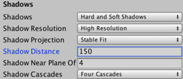
阴影贴图应该是有限的,它覆盖的面积越大,阴影的分辨率越低。 Unity提供了绘制阴影的最大距离,此距离可以通过_Edit / Project Settings / Quality_进行调整。
当阴影几乎快达到了该限定距离就会淡出,Unity内置的shader是这样设定并计算。由于我将手动采样该阴影纹理,当到达纹理的边缘时阴影会被截取,结果是阴影虽然消失了,但有被急剧切割的生硬画面。
要渐隐阴影,首先要知道的是阴影完全消失的距离。该距离又依赖于阴影投射方向。在Stable Fit模式下,以map的中心点呈球面形开始渐隐消失阴影;在Close Fit模式它是依赖于视野深度。
UnityComputeShadowFadeDistance函数能计算出正确距离,它需要两个参数:world pos 和 view depth;然后返回距离A。 注意:该距离A是从阴影纹理的中心点位置或者未更改的视野深度开始计算的。
1
2
3
4
5
6
7
8
9
10
11
UnityLight CreateLight (float2 uv, float3 worldPos, float viewZ) {
    UnityLight light;
    light.dir = -_LightDir;
    float shadowAttenuation = 1;
    #if defined(SHADOWS_SCREEN)
        shadowAttenuation = tex2D(_ShadowMapTexture, uv).r;
        float shadowFadeDistance = UnityComputeShadowFadeDistance(worldPos, viewZ);
    #endif
    light.color = _LightColor.rgb * shadowAttenuation;
    return light;
}
阴影应该是快要接近渐隐距离时开始消失,一旦到达就完全消失。UnityComputeShadowFade函数计算合适的消失因子。
1
2
float shadowFadeDistance = UnityComputeShadowFadeDistance(worldPos, viewZ);
float shadowFade = UnityComputeShadowFade(shadowFadeDistance);
UnityComputeShadowFade 定义在UnityShadowLibrary.cginc,见下:
1
2
3
4
5
6
7
8
float UnityComputeShadowFadeDistance (float3 wpos, float z) {
    float sphereDist = distance(wpos, unity_ShadowFadeCenterAndType.xyz);
    return lerp(z, sphereDist, unity_ShadowFadeCenterAndType.w);
}

half UnityComputeShadowFade(float fadeDist) {
    return saturate(fadeDist * _LightShadowData.z + _LightShadowData.w);
}
阴影渐隐值范围是[0, 1],该值决定了阴影要消失多少。实际的消失值可以加到阴影衰减之上并限定在[0, 1]之内
1
2
float shadowFade = UnityComputeShadowFade(shadowFadeDistance);
shadowAttenuation = saturate(shadowAttenuation + shadowFade);
最后,提供世界坐标和视图深度在片元程序中创建光照。视图深度是片元在视图空间中的位置的Z分量。
1
UnityLight light = CreateLight(uv, worldPos, viewPos.z);
Light Cookies
支持Cookies纹理,使用变量 _LightTexture0 访问;同时还要从world-space转换到light-space,最后采样。转换矩阵使用 _unity_WorldToLight 矩阵变量
1
2
sampler2D _LightTexture0;
float4x4 unity_WorldToLight;
在 CreateLight,使用上述矩阵变量转换world-space到light-space;然后使用转换后的坐标采样cookie纹理。cookie也要衰减,需要单独定义并使用。
1
2
3
4
5
6
7
8
9
light.dir = -_LightDir;
float attenuation = 1;
float shadowAttenuation = 1;
#if defined(DIRECTIONAL_COOKIE)
    float2 uvCookie = mul(unity_WorldToLight, float4(worldPos, 1)).xy;
    attenuation *= tex2D(_LightTexture0, uvCookie).w;
#endif
    //...
light.color = _LightColor.rgb * (attenuation * shadowAttenuation);
整体结果似乎可以,但是观察边缘似乎有硬边
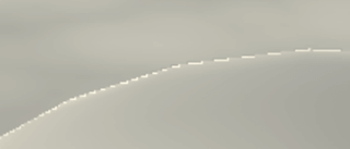
相邻片元的cookie坐标的巨大差异就会导致该问题出现。在这种情况下,GPU选择的mipmap级别对于最近的表面是low level。解决办法之一就是:在采样mip映射时应用偏移。大v的总结
1
attenuation *= tex2Dbias(_LightTexture0, float4(uvCookie, 0, -8)).w;
支持LDR Supporting LDR
上述只支持HDR,现在来支持LDR。步骤如下:
首先,编码后的LDR颜色要乘如light-buffer,而不是加法。这可以用:Blend DstColor Zero实现。注意只用该Blend mode会引起HDR的错误。所以需要灵活配置:Blend [_SrcBlend] [_DstBlend]
然后,使用 $2^{-c}$ 函数解码
1
2
3
4
5
6
7
8
float4 color = UNITY_BRDF_PBS(
        albedo, specularTint, oneMinusReflectivity, smoothness,
        normal, viewDir, light, indirectLight
);
    #if !defined(UNITY_HDR_ON)
        color = exp2(-color);
    #endif
return color;
聚光源 Spotlights
因为方向光会影响到场景内所有物体,所以被画成全屏quad。相比之下,聚光灯只会影响位于圆锥体内的部分物体。通常不需要计算整个图像的聚光灯光照,将绘制一个与聚光灯的影响范围相匹配的金字塔体。
Drawing a Pyramid
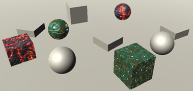
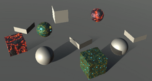
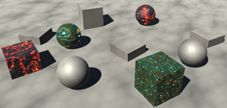
禁用方向灯,改用聚光灯。因为着色器只对方向光正确工作,那么现在的结果会出现错误。但是它仍可以让你看到金字塔的哪些部分被渲染了。
根据上图,金字塔是作为一个普通的3D对象呈现的。它的背面被剔除,所以我们可以看到金字塔的正面。只有当它前面没有东西的时候,它才会被画出来。除此之外,还添加了一个pass,用于设置模板缓冲区,以将绘图限制为位于金字塔卷内的片段。您可以通过frame-debugger来验证。
这意味着我们的着色器的culling和z-test设置被否弃了。 因此将其从着色器中删除。
1
2
3
4
Blend [_SrcBlend] [_DstBlend]
//Cull Off
//ZTest Always
ZWrite Off
当聚光灯的体积距离相机足够远时,此方法适用。 但是,当聚光灯离摄像机太近时,它会失败。 发生这种情况时,相机可能会进入了该体积内。 甚至有可能将近平面的一部分置于其内部,而将其余部分置于其外部,与近平面相交了。 在这些情况下,模板缓冲区不能用于限制渲染。
仍然渲染光照的技巧是绘制金字塔的内表面,而不是金字塔的外表面。 这是通过渲染其背面而不是其正面来完成的。 而且,仅当这些表面最终位于已渲染的表面之后时才渲染它们。 这种方法还涵盖了聚光灯体积内的所有片段。 但这最终导致渲染了太多的碎片,因为通常金字塔的通常隐藏部分也将被渲染。 因此,仅在必要时执行。
支持多光源 Supporting Multiple Light Types
目前,CreateLight只能用于方向光。让我们确保特定于方向灯的代码只在适当的时候使用。
1
2
3
4
5
6
7
8
9
10
11
12
13
14
15
16
17
18
19
20
21
22
23
24
25
26
27
UnityLight CreateLight (float2 uv, float3 worldPos, float viewZ) {
    UnityLight light;
    //light.dir = -_LightDir;
    float attenuation = 1;
    float shadowAttenuation = 1;

    #if defined(DIRECTIONAL) || defined(DIRECTIONAL_COOKIE)
        light.dir = -_LightDir;

        #if defined(DIRECTIONAL_COOKIE)
            float2 uvCookie = mul(unity_WorldToLight, float4(worldPos, 1)).xy;
            attenuation *= tex2Dbias(_LightTexture0, float4(uvCookie, 0, -8)).w;
        #endif

        #if defined(SHADOWS_SCREEN)
            shadowAttenuation = tex2D(_ShadowMapTexture, uv).r;
            float shadowFadeDistance = UnityComputeShadowFadeDistance(worldPos, viewZ);
            float shadowFade = UnityComputeShadowFade(shadowFadeDistance);
            shadowAttenuation = saturate(shadowAttenuation + shadowFade);
        #endif
    #else
        light.dir = 1;
    #endif

    light.color = _LightColor.rgb * (attenuation * shadowAttenuation);
    return light;
}
尽管阴影衰落基于方向阴影贴图,但是其他类型的阴影也应该会被渐隐。 这样可以确保所有阴影都以相同的方式渐隐,而不仅仅是某些阴影。 因此,只要有阴影,阴影淡入淡出代码便适用于所有灯光。 因此,让我们将该代码移到特定于光源的块之外。
我们可以使用布尔值来控制是否使用阴影淡出代码。由于布尔值是一个常数值,如果它仍然为假,代码将被删除。
1
2
3
4
5
6
7
8
9
10
11
12
13
14
15
16
17
18
19
20
21
22
23
24
25
26
27
UnityLight CreateLight (float2 uv, float3 worldPos, float viewZ) {
    UnityLight light;
    float attenuation = 1;
    float shadowAttenuation = 1;
    bool shadowed = false;
    #if defined(DIRECTIONAL) || defined(DIRECTIONAL_COOKIE)
        //省略代码
        #if defined(SHADOWS_SCREEN)
            shadowed = true;
            shadowAttenuation = tex2D(_ShadowMapTexture, uv).r;
        // float shadowFadeDistance = UnityComputeShadowFadeDistance(worldPos, viewZ);
        // float shadowFade = UnityComputeShadowFade(shadowFadeDistance);
        // shadowAttenuation = saturate(shadowAttenuation + shadowFade);
        #endif
    #else
        light.dir = 1;
    #endif

    if (shadowed) {
        float shadowFadeDistance = UnityComputeShadowFadeDistance(worldPos, viewZ);
        float shadowFade = UnityComputeShadowFade(shadowFadeDistance);
        shadowAttenuation = saturate(shadowAttenuation + shadowFade);
    }

    light.color = _LightColor.rgb * (attenuation * shadowAttenuation);
    return light;
}
非方向灯光都有一个position变量。它通过内置的 _LightPos提供。
1
float4 _LightColor, _LightDir, _LightPos;
现在可以确定聚光灯的光向量得出光方向。
1
2
3
4
#else
    float3 lightVec = _LightPos.xyz - worldPos;
    light.dir = normalize(lightVec);
#endif
World Position Agin
结果为黑色,似乎光线方向不正确。 发生这种情况是因为聚光灯的世界位置计算不正确。 当我们在场景中的某个地方渲染金字塔时,不像方向光那样渲染全屏quad将光线存储在normal通道中。 而必须是经由Vertex-Program从顶点的位置发射射线,通过将顶点的pos转换到view-space完成计算,为此,我们可以使用UnityObjectToViewPos函数。
1
i.ray = UnityObjectToViewPos(v.vertex);
然而,这会产生方向错误的光线。我们要消去它们的X和Y坐标。
1
i.ray = UnityObjectToViewPos(v.vertex) * float3(-1, -1, 1);
再次看看UnityObjectToViewPos内部实现
1
2
3
inline float3 UnityObjectToViewPos (in float3 pos) {
    return mul(UNITY_MATRIX_V, mul(unity_ObjectToWorld, float4(pos, 1.0))).xyz;
}
当渲染方向光时,应该只使用顶点法线。当渲染非方向灯以外的光几何时,需要把顶点pos转到view-space计算。Unity通过 _LightAsQuad 变量告诉我们正在处理哪种情况。
如果 _LightAsQuad 被设为1,则处理的是方向光quad并且可以使用法线。否则,我们必须使用UnityObjectToViewPos。插值好过if ==> from + (to – from) * t, t为1直接使用法线,为0直接计算到view-space
1
2
3
4
5
6
i.ray = lerp
(
    UnityObjectToViewPos(v.vertex) * float3(-1, -1, 1),
    v.normal,
    _LightAsQuad
);
锥形衰减 Cookie Attenuation
聚光灯的锥形衰减是通过cookie纹理创建的,无论是默认的圆形还是定制的cookie。我们可以从复制定向光的cookie代码,仿照着写。也是存储在 _LightTexture0
1
2
3
4
float3 lightVec = _LightPos.xyz - worldPos;
light.dir = normalize(lightVec);
float2 uvCookie = mul(unity_WorldToLight, float4(worldPos, 1)).xy;
attenuation *= tex2Dbias(_LightTexture0, float4(uvCookie, 0, -8)).w;
但是,聚光灯Cookie越远离灯光位置,它就会变得越大。 这是由于通过透视变换造成的。 因此,矩阵乘法会产生4D齐次坐标。 为了得到规则的2D坐标,我们必须将X and Y除以W。
1
2
3
float4 uvCookie = mul(unity_WorldToLight, float4(worldPos, 1));
uvCookie.xy /= uvCookie.w;
attenuation *= tex2Dbias(_LightTexture0, float4(uvCookie.xy, 0, -8)).w;
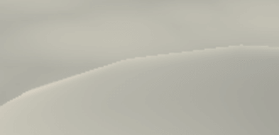
上图实际上产生了两个光锥,一个向前一个向后。 后向圆锥通常在渲染区域之外结束,但这并不能保证。我们只需要前向锥,它对应于负的W坐标。
1
2
attenuation *= tex2Dbias(_LightTexture0, float4(uvCookie.xy, 0, -8)).w;
attenuation *= uvCookie.w < 0;
距离衰减 Distance Attenuation
聚光灯发出的光也会根据距离衰减。此衰减存储在查找纹理中,可通过 _LightTextureB0 使用该纹理。
1
sampler2D _LightTexture0, _LightTextureB0;
纹理被设计成必须使用光的距离的平方,并按光的范围进行缩放,作为UV进行采样。范围存储在 _LightPos的第四个分量中。采样得到的纹理应该使用哪个通道在不同的平台,由 _UNITY_ATTEN_CHANNEL 宏定义。
1
2
3
4
5
6
7
light.dir = normalize(lightVec);
attenuation *= tex2D
(
    _LightTextureB0,
    (dot(lightVec, lightVec) * _LightPos.w).rr
).UNITY_ATTEN_CHANNEL;
float4 uvCookie = mul(unity_WorldToLight, float4(worldPos, 1));
Shadows
当聚光灯有阴影时,定义SHADOWS_DEPTH关键字。
1
2
3
4
5
6
7
8
//在CreateLight中
float4 uvCookie = mul(unity_WorldToLight, float4(worldPos, 1));
uvCookie.xy /= uvCookie.w;
attenuation *= tex2Dbias(_LightTexture0, float4(uvCookie.xy, 0, -8)).w;

#if defined(SHADOWS_DEPTH)
    shadowed = true;
#endif
聚光灯和方向灯使用相同的变量来采样阴影贴图。在聚光灯的情况下,可以使用内置UnitySampleShadowmap来处理采样硬阴影或软阴影的细节。参数:阴影空间中的片元位置。unity_WorldToShadow_(4x4)_矩阵中第一个数组可以用来将世界空间转换为阴影空间。
1
2
3
4
shadowed = true;
shadowAttenuation = UnitySampleShadowmap(
    mul(unity_WorldToShadow[0], float4(worldPos, 1))
);
点光源 Point Lights
点光源使用与聚光灯相同的光向量、方向和距离衰减。这样他们就可以共享代码.应该只在定义SPOT关键字时使用spotlight代码的其余部分。
1
2
3
4
5
6
7
8
9
10
11
12
13
14
15
16
17
18
19
20
21
22
23
24
25
26
#if defined(DIRECTIONAL) || defined(DIRECTIONAL_COOKIE)
    //...
#else
    float3 lightVec = _LightPos.xyz - worldPos;
    light.dir = normalize(lightVec);

    attenuation *= tex2D(
        _LightTextureB0,
        (dot(lightVec, lightVec) * _LightPos.w).rr
    ).UNITY_ATTEN_CHANNEL;

    #if defined(SPOT)
        float4 uvCookie = mul(unity_WorldToLight, float4(worldPos, 1));
        uvCookie.xy /= uvCookie.w;
        attenuation *=
            tex2Dbias(_LightTexture0, float4(uvCookie.xy, 0, -8)).w;
        attenuation *= uvCookie.w < 0;

        #if defined(SHADOWS_DEPTH)
            shadowed = true;
            shadowAttenuation = UnitySampleShadowmap(
                mul(unity_WorldToShadow[0], float4(worldPos, 1))
            );
        #endif
    #endif
#endif
这已经足够让点光源工作了。它们被渲染成和聚光灯一样的效果,除了渲染范围使用的是球形而不是锥形。
Shadows
点光源的阴影存储在一个CubeMap。内置UnitySampleShadowmap可采样。参数:光的方向。一个从光到表面的向量。它是光的相反方向。
1
2
3
4
5
6
7
8
#if defined(SPOT)
//...
#else
    #if defined(SHADOWS_CUBE)
        shadowed = true;
        shadowAttenuation = UnitySampleShadowmap(-lightVec);
    #endif
#endif
Cookies
Point light cookie也可以通过 _LightTexture0获得。需要的是一个cubeMap映射,而不是常规的纹理。
1
2
3
4
5
6
7
8
9
//sampler2D _LightTexture0, _LightTextureB0;
#if defined(POINT_COOKIE)
    samplerCUBE _LightTexture0;
#else
    sampler2D _LightTexture0;
#endif

sampler2D _LightTextureB0;
float4x4 unity_WorldToLight;
要对cookie进行采样,请将片段的world-space转换为light-space,并使用光照空间对立方体映射进行采样。
1
2
3
4
5
6
7
8
9
10
11
#else
    #if defined(POINT_COOKIE)
        float3 uvCookie = mul(unity_WorldToLight, float4(worldPos, 1)).xyz;
        attenuation *= texCUBEbias(_LightTexture0, float4(uvCookie, -8)).w;
    #endif

    #if defined(SHADOWS_CUBE)
        shadowed = true;
        shadowAttenuation = UnitySampleShadowmap(-lightVec);
    #endif
#endif
Skipping Shadows
现在,我们可以使用自己的着色器渲染所有动态光源。 尽管我们目前并未对优化进行太多关注,但仍有一项潜在的大型优化值得考虑:最终超出阴影渐隐距离的片元将不会被阴影化。 但是现在仍在采样它们的阴影,这可能很昂贵。 我们可以通过基于阴影衰落因 子进行 _UNITY_BRANCH_分支来避免这种情况。 它接近1,那么我们可以完全跳过阴影衰减。
1
2
3
4
5
6
7
8
9
if (shadowed) {
    float shadowFadeDistance = UnityComputeShadowFadeDistance(worldPos, viewZ);
    float shadowFade = UnityComputeShadowFade(shadowFadeDistance);
    shadowAttenuation = saturate(shadowAttenuation + shadowFade);
    UNITY_BRANCH
    if (shadowFade > 0.99) {
        shadowAttenuation = 1;
    }
}
但是,即使用了 _UNITY_BRANCH_分支它本身也很昂贵。除了靠近阴影区域的边缘,所有碎片都落在阴影区域的内部或外部。 但这仅在GPU可以利用这一点的情况下才重要。 在这种情况下,使用HLSLSupport.cginc定义UNITY_FAST_COHERENT_DYNAMIC_BRANCHING宏。
1
2
3
4
5
6
#if defined(UNITY_FAST_COHERENT_DYNAMIC_BRANCHING)
    UNITY_BRANCH
    if (shadowFade > 0.99) {
        shadowAttenuation = 1;
    }
#endif
即使这样,仅当阴影需要多个纹理样本时才值得使用。 对于柔和的聚光灯和点光源阴影,进一步使用用SHADOWS_SOFT关键字指示。 而方向光阴影始终只需要单个纹理,因此它性能很便宜。
\[射线对应的Z值 ={射线击中物体时的长度\over射线总长度}\]1
2
3
4
5
6
#if defined(UNITY_FAST_COHERENT_DYNAMIC_BRANCHING) && defined(SHADOWS_SOFT)
UNITY_BRANCH
if (shadowFade > 0.99) {
shadowAttenuation = 1;
}
#endif